
Technical Resources
Metallic Mirror vs Dielectric Mirror: How to Choose
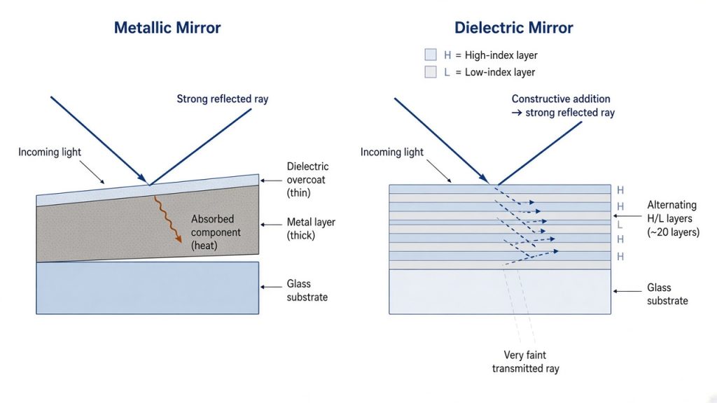
The choice between a metallic mirror and a dielectric mirror comes down to one trade: bandwidth versus reflectance. A metallic mirror reflects moderately well (roughly 90% to 98%) across an extremely wide spectral range and barely cares about angle of incidence. A dielectric mirror reflects extremely well (99% to more than 99.9%) but only inside a designed stopband, at a designed angle, and it shifts when you move away from either.
If your system is broadband, low power, or uses many angles, choose metal. If your system runs a fixed laser line, needs low loss, or handles significant power, choose a dielectric stack.
Quick comparison
| Property | Metallic mirror | Dielectric mirror |
|---|---|---|
| Reflection mechanism | Free-electron response of the metal film | Interference in a multilayer quarter-wave stack |
| Usable bandwidth | Very broad, often an octave or more | Limited stopband, typically 10% to 35% of the center wavelength |
| Typical reflectance | 90% to 98% average | Above 99%, up to 99.9%+ for laser lines |
| Loss mechanism | Absorption in the metal | Transmission leakage and scatter, very low absorption |
| Angle sensitivity | Weak | Strong, the band shifts blue as angle increases |
| Polarization sensitivity | Small but nonzero phase difference | Large split between s and p at high angles |
| Laser damage threshold | Low | High |
| Layer count | 1 metal layer plus 1 to 3 protective layers | 20 to 60+ layers, sometimes more |
| Relative cost | Low | Moderate to high |
How a metallic mirror reflects light
A metal reflects because its conduction electrons respond to the incident field and re-radiate it. That response is described by a complex refractive index, N = n + ik, where the extinction coefficient k is large. At normal incidence the Fresnel result is:
R = [(n − 1)² + k²] / [(n + 1)² + k²]
For aluminum near 550 nm, with n around 0.96 and k around 6.7, this gives about 92%. For silver at the same wavelength, k is similar but n is far smaller, and R rises to about 98%. The remaining few percent is absorbed, not transmitted, because the field decays inside the metal within a skin depth of δ ≈ λ / (4πk), roughly 7 nm for aluminum in the visible. This is why a few hundred nanometers of evaporated metal is optically opaque, and why the reflectance is set almost entirely by the material rather than by film thickness.
That absorption is the defining limitation. Every reflection costs you 2% to 10%, the lost energy becomes heat in a very thin layer, and in a folded optical train the losses compound. Eight aluminum reflections at 92% deliver about 51% of the input.
Aluminum, silver, and gold
Aluminum is the default. It works from the deep ultraviolet through the far infrared, forms a self-limiting Al₂O₃ layer that keeps bare films stable, and is inexpensive. Its weakness is a reflectance dip in the near infrared, centered near 800 to 900 nm, caused by an interband transition. If your system runs a 780 nm or 850 nm source, aluminum is the wrong metal.
Silver gives the highest visible and near-infrared reflectance of any practical metal, but it rolls off below roughly 400 nm and tarnishes when exposed to sulfur compounds and humidity. Protected silver coatings add a dielectric overcoat, and edge sealing matters as much as the overcoat itself.
Gold is the infrared workhorse. It is chemically inert and highly reflective from about 600 nm out past 20 µm, but useless in the blue and green.
Enhanced metals sit between the two families. A few dielectric layers on top of the metal raise reflectance over a chosen band, typically to 95% or better in the visible, without giving up much of the metal’s broadband character. They are a genuine middle option and are often the right answer when a pure dielectric stack is too narrow and bare metal is too lossy.
How a dielectric mirror reflects light
A dielectric mirror, also called a Bragg reflector or a high-reflector (HR) coating, contains no metal. It is a stack of alternating high-index and low-index layers, each one quarter-wave optical thickness (QWOT) at the design wavelength λ₀. Common material pairs are Ta₂O₅/SiO₂ and TiO₂/SiO₂ in the visible and near infrared, and HfO₂/SiO₂ or Al₂O₃/SiO₂ in the ultraviolet.
Each interface reflects a small amplitude. Because each layer contributes a quarter wave of path, all those weak reflections return in phase at λ₀ and add constructively. Reflectance climbs toward unity as pairs are added, so a designer buys reflectance with layer count. Going from 99% to 99.9% is not a small step: it means more layers, tighter thickness control, and usually ion beam sputtering (IBS) rather than conventional electron-beam evaporation.
The stopband width is set by index contrast, not by layer count. A useful estimate is that the first-order stopband runs from λ₀/(1 + x) to λ₀/(1 − x), where
x = (2/π) · arcsin[(n_H − n_L) / (n_H + n_L)]
For a TiO₂/SiO₂ pair with n_H ≈ 2.35 and n_L ≈ 1.46, x is about 0.15. A stack designed for 1064 nm therefore holds high reflectance from roughly 925 nm to 1250 nm. Swap to the lower-contrast Ta₂O₅/SiO₂ pair and that band narrows to about 955 nm to 1200 nm. Outside the stopband, reflectance drops and the curve breaks into ripple, and odd-harmonic stopbands reappear near λ₀/3 and λ₀/5.
This is the essential asymmetry between the two families. With a metal you get bandwidth for free and pay for it in absorption. With a dielectric stack you get reflectance by adding layers and pay for it in bandwidth, angle tolerance, and cost.
Reflectance and bandwidth side by side
Typical catalog values from established optics suppliers are shown below. They are representative of the coating class, not guarantees, and specific numbers always depend on the design and the deposition process.
| Coating | Usable range | Typical average reflectance | Watch out for |
|---|---|---|---|
| UV-enhanced aluminum | ~250 to 400 nm | ~85% to 90% | SiO₂ overcoats absorb below ~250 nm, MgF₂ is used instead |
| Protected aluminum | ~400 nm to far IR | >90% visible | Dip near 800 to 900 nm |
| Enhanced aluminum | ~450 to 650 nm | >95% | Narrower useful band than protected aluminum |
| Protected silver | ~450 nm to 20 µm | >97% (450 nm to 2 µm), >95% (2 to 20 µm) | Rolls off below ~400 nm, tarnish risk |
| Protected gold | ~800 nm to 20 µm | >96% | Very low reflectance below ~600 nm |
| Broadband dielectric | Designed band, e.g. 400 to 750 nm | >99% | Reflectance falls off a cliff outside the band |
| Laser-line dielectric | Single line at a stated AOI | >99.5%, often >99.9% | Useless at any other wavelength or angle |
Angle of incidence and polarization
Angle of incidence (AOI) is where most mirror specifications go wrong.
A metallic mirror is nearly angle independent in reflectance out to steep angles. It is not, however, polarization neutral. At non-normal incidence a metal introduces a differential phase shift between s-polarized and p-polarized light, which converts linear polarization into elliptical polarization. In ellipsometry, polarization-maintaining beam paths, and any system with a downstream polarizer, that phase difference is a real error source and needs to be specified, not assumed away.
A dielectric mirror behaves differently. The whole stopband shifts toward shorter wavelengths as AOI increases, approximately as:
λ(θ) = λ₀ · √[1 − (n₀ sin θ / n_eff)²]
where n_eff is the effective index of the stack. For a typical near-infrared design with n_eff near 1.9, moving from 0° to 45° pulls the center wavelength down by roughly 7%. A mirror designed for 1064 nm at normal incidence lands near 990 nm when you fold it at 45°, and your laser line can end up on the falling edge of the band.
At the same time, s and p separate. The s-polarized stopband is wider and the p-polarized stopband is narrower, so at 45° a stack can hold 99.8% for s and considerably less for p. If the source is unpolarized or the polarization state rotates, specify performance for both, or specify Ravg and accept the ripple.
For femtosecond systems there is a third parameter: group delay dispersion (GDD). Light penetrates a dielectric stack to a wavelength-dependent depth, which stretches the pulse. Standard HR coatings can add tens to hundreds of fs² per bounce. Low-GDD or dispersion-compensating designs exist for this reason, and protected silver is often preferred for broadband ultrafast beams because its penetration depth is negligible.
Power handling and laser damage
Laser-induced damage threshold (LIDT) is where the two families separate most sharply, and it follows directly from the absorption difference.
In the nanosecond regime, protected aluminum mirrors are commonly tested in the range of a few tenths of a joule per square centimeter at 1064 nm with 10 ns pulses. Protected silver does somewhat better, enhanced silver better again, and quality dielectric HR coatings reach values one to two orders of magnitude higher. The reason is simple: the metal converts a percentage of every pulse into heat inside a 10 nm layer, while the dielectric stack spreads a much smaller absorbed fraction across a micron of low-absorption oxide.
Three rules keep LIDT comparisons honest:
- LIDT in the nanosecond regime scales roughly with the square root of pulse duration, so a 10 ns number does not transfer to a 5 ns or 100 ns pulse without conversion.
- LIDT scales approximately with the square root of wavelength, so a 1064 nm value overstates performance at 532 nm and badly overstates it at 355 nm.
- In the picosecond and femtosecond regimes the damage mechanism changes from thermal to field-driven ionization, and the scaling rules above stop working.
Cleanliness dominates all of it. Published LIDT values are measured on clean optics, and surface contamination routinely cuts the real threshold by a large factor. A fingerprint on a fold mirror is a more common cause of failure than an incorrect coating choice.
For continuous-wave (CW) operation, average power and thermal distortion matter more than LIDT. A few percent absorption on a metallic mirror at several hundred watts produces enough of a thermal gradient to distort surface figure and steer the beam.
The rest of the datasheet
Coating type is only one line of the specification. For precision optical mirrors and custom optical coatings, suppliers such as GIAI Photonics will also ask for the parameters below, and leaving them blank means accepting the default.
| Parameter | Convention | Comment |
|---|---|---|
| Surface figure | λ/4, λ/10, λ/20 P-V at 632.8 nm | Tighter figure raises cost fast, especially on large apertures |
| Surface quality | Scratch-dig per MIL-PRF-13830B, or ISO 10110-7 | 60-40 general purpose, 20-10 laser, 10-5 demanding |
| Clear aperture | Typically 85% to 90% of diameter | Coating uniformity degrades toward the edge |
| AOI and polarization | State both, always | 0°, 45°, or a range, plus s, p, or unpolarized |
| Reflectance spec | Ravg or Rabs over a stated band | Ravg hides narrow dips, Rabs does not |
| Substrate | N-BK7, fused silica, Zerodur, silicon, copper | Fused silica for UV and thermal stability, metal for cooled optics |
| Environmental durability | Adhesion, abrasion, humidity | MIL-C-48497 and MIL-M-13508 are the usual references |
| Wedge and back surface | Wedge angle, back-surface AR or fine grind | Relevant for partially transmitting dielectric mirrors |
Common specification mistakes
Ordering a 0° mirror and installing it at 45°. This is the single most frequent dielectric mirror failure. The stopband shifts blue by several percent, the laser line drifts toward the band edge, reflectance drops from 99.9% to something unpleasant, and the loss shows up as heating in the mount.
Specifying Ravg when the application needs Rabs. An average of 99% across 400 to 750 nm is compatible with a dip to 97% at your actual wavelength. If a single line matters, specify the absolute minimum at that line.
Using aluminum near 800 nm. The interband dip is well documented and still catches people who select the coating by price rather than by reflectance curve.
Assuming a dielectric mirror is opaque. A 99.9% HR coating still transmits about 0.1%. At 100 W that is 100 mW leaking through the substrate onto whatever sits behind it. Either use the leakage deliberately for power monitoring or block it.
Putting protected silver in an uncontrolled environment. Protective overcoats slow tarnish, they do not stop it, and unsealed edges are the usual entry path. In humid or sulfur-bearing air, enhanced aluminum is often the more reliable long-term choice even though it starts out less reflective.
Comparing LIDT numbers measured under different conditions. Wavelength, pulse duration, repetition rate, and beam diameter all have to match before two numbers mean anything.
How to choose
- Broadband imaging, telescopes, spectrometer fold mirrors: protected or enhanced aluminum. Bandwidth and angle tolerance beat the last few percent of reflectance.
- Visible to near-infrared with many bounces: protected silver, if the environment is controlled.
- Thermal imaging, CO₂ laser delivery, FTIR: protected gold, or gold on a copper substrate when cooling is needed.
- Single-wavelength laser systems, resonator optics, high pulse energy: dielectric laser-line HR, specified at the actual AOI and polarization.
- Fluorescence and machine vision, where the mirror also separates bands: dichroic and interference filter designs rather than a simple HR.
- Broadband femtosecond pulses: protected silver for low dispersion, or a purpose-designed low-GDD dielectric mirror.
FAQ
Can a dielectric mirror be broadband like a metal one? Partially. Broadband dielectric designs cover ranges such as 400 to 750 nm by stacking sub-stacks of different design wavelengths, and they hold above 99% inside that range. They cannot match the octave-spanning coverage of silver or gold, and the extra layers raise both cost and sensitivity to deposition error.
Why does my dielectric mirror perform worse than the datasheet? Check AOI first, polarization second. A curve measured at 0° tells you very little about performance at 45°. After that, check whether the specification was Ravg over a band rather than absolute reflectance at your line.
Is protected aluminum good enough for a low-power laser? Often yes, below roughly a milliwatt per square centimeter of CW intensity, provided the 8% loss per bounce is acceptable and the wavelength avoids the 800 to 900 nm dip. For pulsed sources, run the LIDT calculation rather than assuming.
Does a metallic mirror change polarization? Yes, at non-normal incidence. Reflectance for s and p differs slightly, and more importantly the two components pick up different phase shifts, turning linear polarization elliptical. Below about 10° AOI the effect is usually negligible.
What surface figure do I actually need? For imaging and beam quality, λ/10 P-V is a common working point, and λ/20 is used for interferometry and demanding resonators. λ/4 is adequate for illumination and non-critical folds. Each step tightens the polishing requirement and increases price, so specify at the level the system error budget actually requires.
Why is IBS coating more expensive than e-beam? Ion beam sputtering produces denser films with lower scatter, lower absorption, and much better thickness repeatability, which is what makes reflectance above 99.9% and stable spectral performance achievable. The deposition rate is slower and the equipment cost is higher, and both show up in the price.
If you are matching a mirror coating to a specific wavelength, angle, and power level, GIAI Photonics supplies optical mirrors, dichroic filters, and custom optical coatings built to a stated reflectance and AOI specification.
