
Technical Resources
Narrow Bandpass Filter Manufacturer: How to Specify
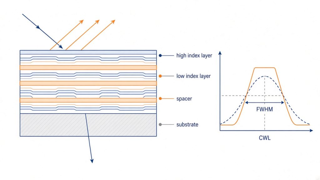
Choosing a narrow bandpass filter manufacturer comes down to three questions: can their coating process hold your center wavelength tolerance across the full clear aperture, do they measure the filter under your actual angle and cone conditions, and is the blocking specification real across your detector’s entire response range? A supplier that answers those three clearly is usually a supplier you can build a system around. Price, catalog size, and lead time matter, but they are the second conversation, not the first.
This article covers the physics that sets the limits, the datasheet parameters that carry real risk, and the specification mistakes that cause instruments to fail integration.
What makes a bandpass filter “narrow”
A narrow bandpass filter is a thin-film Fabry-Perot interference structure. Two quarter-wave dielectric mirror stacks sandwich a half-wave (or multiple half-wave) spacer layer, forming a resonant cavity that transmits at one wavelength and reflects everything nearby. Stacking two, three, or four such cavities in series steepens the edges and flattens the top of the passband.
“Narrow” is a ratio, not an absolute number. A 10 nm full width at half maximum (FWHM) at 850 nm is about 1.2 percent of the center wavelength (CWL) and is routine. The same 10 nm at 250 nm is 4 percent and is a much easier coating. Filters below roughly 1 percent of CWL are where manufacturing capability starts to separate suppliers.
The reason is layer thickness control. CWL scales directly with the optical thickness of the stack, so a CWL tolerance of plus or minus 0.2 nm at 532 nm demands optical thickness accuracy near 0.04 percent, held consistently across dozens of layers and across the whole coating fixture. That requirement, not the design file, is what a narrow bandpass filter manufacturer is actually selling you.
Coating process determines most of the datasheet
Ask which deposition process is used before you ask anything else. It predicts the temperature coefficient, the environmental durability, the achievable FWHM, and the cost.
| Process | Typical materials | Moisture behavior | Thermal drift of CWL | Practical notes |
|---|---|---|---|---|
| Evaporated soft coating | ZnS, cryolite (Na3AlF6), PbF2 | Porous and hygroscopic; spectrum shifts with humidity | Roughly an order of magnitude larger than hard oxide coatings | High index contrast makes very narrow bands achievable with fewer layers; must be sealed or laminated between cover glass; cannot be cleaned aggressively |
| Ion-assisted deposition (IAD / PIAD) | Ta2O5, Nb2O5, TiO2, SiO2 | Dense, largely stable | Low | Good balance of throughput and stability; widely used for production NIR filters |
| Magnetron / plasma sputtering | Ta2O5, Nb2O5, SiO2 | Dense, non-hygroscopic | Commonly quoted in the 2 to 5 pm/°C range for hard-coated filters | Standard for ultra-narrow flat-top filters and high layer counts; cleanable, no sealing required |
| Ion beam sputtering (IBS) | Ta2O5, SiO2, HfO2 | Dense | Low | Highest precision and lowest scatter and loss; slowest deposition and highest cost |
Hard oxide coatings have displaced soft coatings in most new designs below about 1200 nm because a single dense stack on one substrate replaces a laminated assembly, survives handling and cleaning, and does not drift with ambient humidity. Soft coatings still appear where extreme index contrast or deep UV performance is needed.
Specifications a narrow bandpass filter manufacturer must commit to
A quotation that lists only CWL, FWHM, and transmission is not a specification. The parameters below are the ones that carry integration risk.
| Parameter | What it means | What to state on the drawing |
|---|---|---|
| CWL | Wavelength at the center of the passband, conventionally the midpoint between the 50 percent transmission points | Nominal value, tolerance, and the AOI it applies to |
| FWHM | Bandwidth between the 50 percent transmission points | Nominal and tolerance; state whether the target is minimum, maximum, or nominal |
| Peak or average transmission | Transmission at CWL, or averaged across a defined band | The band over which it is measured, not just a single number |
| Blocking (optical density, OD) | OD = -log10(T); OD 6 means 10^-6 transmission | Level plus wavelength range plus whether it is peak or average |
| AOI and cone half-angle | Tilt of the filter and the convergence of the beam through it | Both. A filter used at 0° in an f/2 cone is not a 0° filter |
| Temperature coefficient and operating range | CWL drift with temperature, usually in pm/°C | Required passband stability across the full instrument temperature range |
| Clear aperture | Region over which the spectral specification holds | Percentage or dimension; also ask for CWL uniformity across it |
| Surface quality | Scratch-dig, per MIL-PRF-13830B | 80/50, 60/40, or 40/20 depending on where the filter sits in the beam path |
| Transmitted wavefront / parallelism | Optical path distortion introduced by the filter | Required when the filter sits in an imaging path rather than in front of a bare detector |
| Environmental durability | Adhesion, humidity, abrasion, temperature cycling | Reference MIL-C-48497A or ISO 9211-4 and ISO 9022 explicitly if the part is exposed |
Dimensional tolerances, thickness, edge blackening, and mounting also belong on the drawing. Under ISO 10110, surface figure and imperfection specifications can be called out in a standard notation that avoids ambiguity between you and the coating shop.
Angle of incidence: the specification most often left off the drawing
Interference filters blue-shift as the angle of incidence (AOI) increases. The passband moves toward shorter wavelengths according to
λ(θ) = λ0 × sqrt(1 − (sin θ / n_eff)²)
where λ0 is the CWL at normal incidence and n_eff is the effective index of the coating design. Effective index depends on the spacer material, the cavity order, and the polarization state, so it is a design property, not a material constant. Low-index spacer designs land near 1.45, and high-index spacer designs can approach 2.0 or above.
Take an 850 nm filter tilted 10 degrees. With n_eff = 2.0 the CWL moves to about 847 nm, a 3.2 nm shift. With n_eff = 1.45 the same tilt moves it to about 844 nm, a 6.1 nm shift. If the filter has a 10 nm FWHM, the low-index design has spent more than half its passband on tilt alone.
Two consequences follow. First, in a converging beam every ray arrives at a different angle, so the passband is not simply shifted but smeared: the effective bandwidth broadens, the peak transmission drops, and the edges soften. Second, S and P polarizations shift differently because Fresnel reflection at each interface is polarization dependent, which splits the passband at large angles. Ask the manufacturer for the n_eff of the specific design and for a modeled or measured curve at your actual cone angle.
Blocking: an OD number means nothing without a range
Blocking is the whole reason a narrow bandpass filter exists. Three details decide whether the specification is useful.
The range must cover your detector, not your signal. A silicon detector responds from roughly 200 nm to 1100 nm. If your filter is blocked OD 6 from 400 to 900 nm, everything from 900 to 1100 nm reaches the detector unattenuated. Specify blocking across the full spectral response of the detector, and further if any source in the system emits outside it.
Peak versus average matters. Average OD 6 across a wide range can hide a narrow leak of OD 3. For laser-based systems, request blocking specified at the specific wavelengths you must reject, not as a band average.
Ask how it was measured. A standard spectrophotometer runs out of dynamic range somewhere around OD 5 to 6. Deeper blocking is verified with specialized measurement methods or is guaranteed by design and witness sampling. A supplier who claims OD 8 measured on a standard instrument is telling you something about their metrology.
Deep blocking usually comes from combining the interference stack with an absorbing element, either colored glass or a metal-dielectric induced transmission layer. Both cost peak transmission, which is the trade-off you are buying.
The engineering trade-offs
Nothing in a narrow bandpass filter improves for free.
- Narrower FWHM requires more cavities and more layers. Peak transmission falls, cost rises, yield drops, and a fixed angular or thermal shift consumes a larger fraction of the passband.
- Flatter top and steeper edges also require more cavities. A single-cavity filter has a rounded Lorentzian shape with shallow skirts; three or four cavities give a flat top and sharp edges at the price of layer count.
- Deeper blocking over a wider range means added absorbing glass or thicker stacks, which lowers throughput and can add wavefront error.
- Larger clear aperture exposes coating non-uniformity. CWL varies across the coating chamber, so a 50 mm filter with a plus or minus 0.3 nm CWL spec is a far harder part than a 12.5 mm one.
- Tighter CWL tolerance narrows the acceptance window in production. Filters are often sorted from a run, which is why tight-tolerance parts carry longer lead times and higher prices.
Common specification mistakes
Specifying at 0° and using in a cone. The most frequent failure. A 3 nm filter specified at normal incidence, placed in an f/1.4 cone, loses peak transmission and broadens in a way that ruins the signal-to-background calculation the design was based on.
Forgetting that the source drifts too. Fabry-Perot laser diodes typically shift on the order of 0.25 to 0.3 nm/°C, while a hard-coated filter drifts only a few picometers per degree. Over a 40 °C swing the laser can walk several nanometers while the filter stays put. A 3 nm passband that looked generous at the bench temperature clips the signal in the field. The passband must cover the source excursion, the AOI shift, and the manufacturing tolerance combined.
Quoting OD without a range. Covered above, and worth repeating because it is the most common cause of unexplained background in a working instrument.
Using a laminated soft-coated filter in a humid or high-power path. Epoxy edges absorb moisture and the coating degrades; strong absorbed flux heats the laminate.
Ignoring orientation. For filters with an absorbing blocker, the reflective interference side should generally face the source so the absorbing glass does not carry the thermal load.
Accepting a catalog curve as acceptance data. Published curves are typical, and lot-to-lot variation is real. For anything critical, require a measured scan of the delivered lot under defined conditions.
Where narrow bandpass filters are used
Fluorescence instruments use them to separate excitation from emission, where blocking depth sets the detection limit. LiDAR receivers use laser line filters at 905, 940, or 1550 nm to suppress sunlight, where the FWHM budget is dominated by diode drift and receiver cone angle. Machine vision uses NIR bands to make illumination immune to ambient light. Raman spectroscopy and non-dispersive infrared gas sensing rely on narrow passbands sitting close to strong rejected lines. Astronomy uses ultra-narrow filters at emission lines such as H-alpha, often tilt-tuned deliberately using the same angle shift discussed above.
Suppliers such as GIAI Photonics list standard narrow bandpass filters at common NIR and laser wavelengths, with custom CWL, FWHM, substrate, and dimensions available on drawing review, which is the usual path when a catalog part misses one parameter.
How to evaluate a supplier before you commit
Ask these, and judge the answers rather than the catalog:
- Which deposition process, and what layer count does this design require?
- What is n_eff for this design, and can you show the modeled spectrum at my AOI and cone half-angle?
- What is the CWL uniformity across the clear aperture, and part to part within a lot?
- How is the blocking measured, and to what OD does your metrology actually reach?
- What is the temperature coefficient, and over what range is it valid?
- Which durability tests do you run, and can you provide the report?
- Will you supply a measured transmission scan for the delivered lot?
A supplier who answers with design-specific numbers is doing the engineering. A supplier who answers with marketing adjectives is reselling someone else’s coating run.
FAQ
How narrow can a bandpass filter actually be? Commercial hard-coated filters below 1 nm FWHM are produced routinely at common laser wavelengths, and sub-nanometer designs are available for astronomy and spectroscopy. The practical limit is set by layer-thickness control, coating uniformity, and how much peak transmission and cost you will accept, not by the physics of the cavity.
Does a narrower filter always improve signal to noise? No. Narrowing the passband cuts background, but it also cuts signal if the source has spectral width or drifts with temperature, and it makes the filter more sensitive to angle. The optimum bandwidth matches the source linewidth plus the total expected drift, not the smallest number available.
Can I tune a filter by tilting it? Yes, toward shorter wavelengths only, following the effective index relation. Tilt tuning also broadens the passband, reduces peak transmission, and splits S and P polarization. It works well for a few nanometers of correction in collimated beams and poorly in fast converging beams.
Should I specify hard-coated or soft-coated? Default to hard oxide coatings below about 1200 nm. They are dense, cleanable, thermally stable, and need no lamination. Soft coatings remain relevant for deep UV and for designs that need the very high index contrast of ZnS and cryolite, but they must be sealed and handled carefully.
What surface quality do I need? Surface quality per MIL-PRF-13830B affects scatter, not the passband. 60/40 is adequate for a filter in front of a detector. Move to 40/20 or better when the filter sits near a focus or in a low-scatter imaging path, and add a transmitted wavefront specification in that case.
Why do two suppliers quote very different prices for the same specification? Usually process and tolerance. A design met by sorting parts from a large evaporated run costs far less than the same specification held by sputtering with tight CWL uniformity across a large aperture. Compare the measured data and the tolerance commitments, not the headline parameters.
Closing
If you need standard or custom narrow bandpass filters, review the narrow bandpass filter range from GIAI Photonics and send your CWL, FWHM, blocking, AOI, and aperture requirements for a drawing review.
