
Technical Resources
Flat-Top vs Gaussian Bandpass Filter: How to Choose
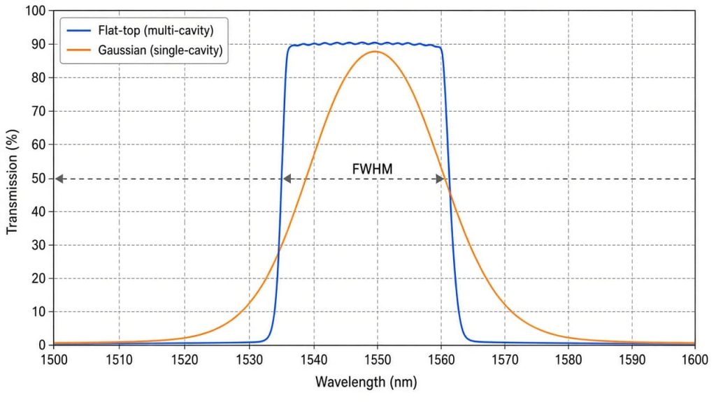
A flat-top bandpass filter holds near-peak transmission across the whole passband and then drops steeply at both edges. A Gaussian bandpass filter reaches maximum transmission only at the center wavelength and falls away gradually on either side. The choice between a flat-top vs Gaussian bandpass filter is not a quality ranking. It is a trade between spectral squareness on one side and angular tolerance, layer count, and cost on the other.
Pick flat-top when the signal wavelength moves, when several bands sit close together, or when you need a defined edge position. Pick Gaussian when the beam is not well collimated, when the source is stable and centered, or when the budget will not carry a 150-layer coating run.
Where the two passband shapes come from
Both shapes come out of the same structure: a Fabry-Perot cavity built from two dielectric mirror stacks separated by a spacer layer of half-wave optical thickness. Resonance occurs when
m·λ = 2·n_s·d·cos(θ_s)
where m is the interference order, n_s and d are the refractive index and physical thickness of the spacer, and θ_s is the ray angle inside the spacer. The mirror reflectance sets the cavity finesse, which sets the full width at half maximum (FWHM). Increase the mirror reflectance or the spacer order and the passband narrows.
A single-cavity filter follows the Airy function, which near resonance is Lorentzian, not Gaussian. Its skirts fall off slowly and its out-of-band attenuation builds up slowly with wavelength. “Gaussian” is trade shorthand for that rounded, peaked profile, and it also gets applied to absorptive colored-glass filters and to simple two-layer-stack designs that produce a similar rounded curve. The distinction matters when you model system throughput, because a Lorentzian tail is much heavier than a Gaussian one.
Squareness comes from adding cavities. Two or more Fabry-Perot cavities joined by coupling layers produce a wider region of high transmission with steeper skirts. Two-cavity designs are known for the twin transmission peaks at the passband edges that coating engineers call rabbit ears. Three, four, and more cavities suppress those peaks and approach a rectangular response. A modern flat-top narrowband filter can carry well over 100 layers.
One point that gets confused in purchasing: passband shape is a design decision (cavity count), while hard coating versus soft coating is a durability and stability decision (deposition process). Ion beam sputtering, ion-assisted deposition, and plasma-assisted sputtering all produce dense, non-hygroscopic films. Those processes make flat-top designs practical, but a hard-coated filter is not automatically flat-top, and a rounded passband is not automatically a cheap soft-coated part.
Reading passband shape off a datasheet
Shape does not appear as a single number. It appears across four or five specifications that engineers often skim.
| Specification | What it tells you about shape |
|---|---|
| CWL (center wavelength) | Midpoint between the cut-on and cut-off 50% points. Not necessarily the peak transmission point |
| FWHM | Width between the two 50% points. Says nothing about what happens between them |
| Peak transmission vs average passband transmission | A Gaussian filter can hit a high peak and still average much lower across the band |
| Passband ripple | Peak-to-valley transmission variation inside the band. The real flatness spec |
| Edge steepness | Wavelength distance from 50% transmission to a stated OD, usually OD6, expressed as a percentage of CWL |
| Blocking range and OD (optical density) | Separate from edge steepness. OD = -log10(T) |
| AOI (angle of incidence) and CHA (cone half angle) | The conditions the whole curve was specified under |
If a datasheet quotes only CWL, FWHM, and peak transmission, you cannot tell the two shapes apart. Ask for the measured transmission scan.
Edge steepness is where flat-top designs earn their price. Published capability from leading hard-coating suppliers such as Alluxa reaches roughly 0.5% of CWL from the 50% transmission point to OD6. At a 532 nm center wavelength, that is under 3 nm of transition. A single-cavity design at the same FWHM needs many times that span to reach the same attenuation.
Blocking range is a separate question. A multi-cavity Fabry-Perot stack only blocks over its own stopband. For a design using SiO2 as the low index material and Nb2O5 as the high index material, that stopband covers roughly λc/1.14 to λc/0.86. Everything outside it leaks unless you add blocking coatings or a colored-glass absorber. Steep edges and deep wideband blocking are two different purchases.
Comparison: flat-top vs Gaussian bandpass filter
| Parameter | Flat-top (multi-cavity) | Gaussian / peaked (single-cavity or absorptive) |
|---|---|---|
| Passband shape | Near-rectangular, high average transmission across the band | Peaked at CWL, transmission drops steadily toward the edges |
| Typical structure | 3 or more coupled cavities, often 100+ layers | 1 to 2 cavities, or colored glass plus a simple stack |
| Edge steepness | Steep, down to about 0.5% of CWL (50% to OD6) for premium designs | Shallow, transition width comparable to the FWHM itself |
| Passband ripple | Present, grows with cavity count and process error | Very low, the curve is inherently smooth |
| Transmission stability under source drift | Nearly constant while the line stays inside the band | Falls off as the line detunes from CWL |
| Cone angle and AOI tolerance | Degrades faster, the flat top can smear or split | Degrades more gracefully, shifts without dramatic shape change |
| Group delay / chromatic dispersion | Higher near the edges, matters for ultra-narrow and short-pulse work | Low |
| Process sensitivity and cost | High, layer thickness errors show up as ripple and loss | Lower |
Ripple deserves a note. Each added cavity has to be matched to its neighbors. Any layer thickness error propagates, so squareness is limited in practice by deposition control and optical monitoring rather than by design theory.
How much signal does a Gaussian shape actually cost?
Work it in transmission at your wavelength, not peak transmission.
For a Gaussian passband, normalized transmission at a detuning Δλ from CWL is:
T(Δλ)/T_peak = exp(-4·ln2·(Δλ/FWHM)²)
For a single-cavity Lorentzian passband:
T(Δλ)/T_peak = 1 / (1 + (2Δλ/FWHM)²)
Take a 10 nm FWHM filter and a laser line that sits 3 nm off center after temperature drift and manufacturing tolerance stack up. The Gaussian filter delivers about 78% of peak transmission. The Lorentzian delivers about 74%. A flat-top filter of the same FWHM delivers essentially its full in-band value, minus ripple.
That 20% plus loss is often the whole argument. In a photon-starved measurement it is the difference between a one-second and a two-second integration.
The reverse case is real too. Integrate a Gaussian curve and the area under it is about 1.06 times FWHM × T_peak, while a perfect rectangle of the same FWHM gives exactly 1.0. For a broadband emitter and no neighboring band to reject, the rounded filter is not throwing away light. It is spreading its acceptance past the nominal band edges, which is exactly what you cannot allow in a multiband system.
AOI, cone angle, and the way a flat top stops being flat
Every interference filter blue-shifts with angle:
λ(θ) = λ₀ · √(1 – sin²θ / n_eff²)
The effective index n_eff is a design property, typically somewhere between about 1.4 and 2.1 depending on the spacer material and the design. Low n_eff means large angular shift and a filter that tunes readily with tilt. High n_eff means better angular stability.
Take n_eff = 1.85 and a CWL of 850 nm. At 10 degrees the band shifts about 0.44%, or 3.7 nm. In an f/2 collection cone, the marginal ray sits near 14 degrees, and the shift at that edge of the cone reaches roughly 0.9%, or about 7.8 nm. The filter does not simply move. It integrates over every angle in the cone, so the passband broadens asymmetrically toward shorter wavelengths and the edges wash out.
Multi-cavity filters suffer more here than single-cavity ones. The rectangular shape depends on phase matching between reflections from different mirror stacks in the structure, and that condition holds only near one angle. Push a sub-nanometer multi-cavity filter a few degrees off design and the flat top can resolve into separate narrow peaks. Add s and p polarization splitting at non-normal incidence and the two polarizations produce two slightly different edge positions.
The practical rule: a flat-top filter only stays flat under the AOI and cone half angle it was specified for. GIAI Photonics and other suppliers of narrow bandpass filters will design to a stated cone angle, but they need that number in the request, not after the first sample fails.
Common specification mistakes
Buying flat-top performance and installing it in a fast cone. A narrowband flat-top filter specified at 0 degrees collimated, dropped into an f/2 imaging path, gives a blue-shifted, broadened, rounded band. You paid for edges you cannot use. Either collimate the beam through the filter or specify the filter for the actual cone half angle and accept a wider design bandwidth.
Treating edge steepness as blocking. A steep edge tells you how fast transmission falls near the band. It says nothing about attenuation 200 nm away. Silicon detectors respond out to about 1100 nm, so a visible filter without extended blocking across the full detector response will pass near-infrared light you never modeled.
Setting FWHM equal to the source linewidth. Budget the sum of CWL manufacturing tolerance, thermal shift, angular shift, and source drift before choosing FWHM. Hard-coated filters typically shift under about 5 ppm of CWL per degree C, roughly 2 to 5 pm/°C in the visible and near infrared. Soft-coated filters can run an order of magnitude higher, which forces tighter thermal control on the instrument.
Comparing suppliers on peak transmission. Two filters quoting 95% peak transmission perform very differently if one averages 93% across the band and the other averages 70%. Ask for average in-band transmission or the scan.
Ignoring ripple in a ratio measurement. In multispectral or ratiometric work, passband ripple that varies filter to filter shows up as channel-to-channel gain error that no calibration constant will fix cleanly.
How to choose by application
Fluorescence emission collection. Flat-top. Emission spectra are broad, the neighboring excitation band is close, and you want maximum area under the curve with a hard cutoff.
Laser line cleanup and Raman excitation. Flat-top with steep edges, so you can place the edge close to the laser line without clipping it.
LiDAR (light detection and ranging) receive path at 905 nm or 1550 nm. Flat-top, sized to cover diode wavelength drift with temperature plus the receive cone angle. This is the classic case where transmission stability across the band beats a high center peak.
Machine vision with a stable LED and a fast lens. Often Gaussian is the sensible choice. The wide cone destroys squareness anyway, and the cost difference is real across hundreds of units.
Multiband and DWDM (dense wavelength division multiplexing) channel filters. Flat-top, no alternative. Adjacent channel isolation is the whole specification.
Cost-driven single-wavelength detection with a temperature-controlled source. Gaussian, with the FWHM opened enough that normal drift never leaves the high-transmission region.
FAQ
Is a flat-top filter always better than a Gaussian one? No. It is better when the wavelength you care about can move within the band, or when something you must reject sits close to the band edge. It is worse when the beam has a large cone angle, when passband ripple would corrupt a ratio measurement, or when the extra layer count is not worth the cost.
How many cavities do I need for a flat top? Squareness improves with cavity count, and useful flatness generally starts around three cavities. Two-cavity designs still show edge peaks. The upper limit is set by deposition control, since each added cavity introduces more ripple and insertion loss if layer thicknesses drift.
Does a Gaussian filter have better angular tolerance? It degrades more gracefully. A single-cavity filter shifts in wavelength under tilt while roughly keeping its shape. A multi-cavity flat-top depends on phase matching between stacks, so its passband can broaden, distort, or split into separate peaks at angles well off design.
Can I use tilt to tune a bandpass filter onto my wavelength? Yes, within limits. Tilting always shifts the band to shorter wavelengths, following λ(θ) = λ₀√(1 – sin²θ/n_eff²). Expect polarization splitting, some transmission loss, and beam displacement through the substrate. Tilt tuning of more than a few degrees works far better on filters designed for it.
What should I send a supplier to get the right passband shape? Send CWL, required FWHM, minimum transmission at your specific wavelengths, blocking OD with the wavelength range over which it applies, AOI and cone half angle, operating temperature range, clear aperture, and substrate and surface requirements such as scratch-dig per MIL-PRF-13830B or surface figure per ISO 10110.
Why does my measured FWHM differ from the datasheet? Measurement conditions. Spectrophotometer bandwidth, beam convergence, sample tilt, and temperature all change the result, and narrow filters are the most sensitive. A filter measured in a converging beam will read wider and blue-shifted compared with the same part in collimated light.
If you are specifying a passband shape for a real optical path rather than a catalog part, GIAI Photonics builds bandpass, narrow bandpass, and custom-coated filters to a defined AOI and cone angle.
