
Technical Resources
Optical Window Focus Shift: Causes & Fixes | GIAI
A protective optical window may be flat, transparent, and free of optical power, yet installing it can change where a camera forms a sharp image. The effect becomes particularly relevant when a glass plate is introduced between an imaging lens and its sensor, where light is already converging toward the image plane.
The primary reason is refraction. When a plane-parallel plate replaces an equivalent thickness of air in a converging beam, the rays travel at smaller angles inside the material. After leaving the plate, they resume their original directions but intersect the optical axis farther downstream. This produces an axial focus shift.
In practical imaging systems, the result also depends on where the window is installed, its thickness and refractive index, the lens numerical aperture, field angle, and whether the optical design already accounts for the window.
A focus shift is not necessarily evidence of a defective window. It may be the predictable consequence of adding a transmissive element to an optical system that was not designed for it.
Why Can a Flat Optical Window Change Focus?
An ideal plane-parallel optical window has no net paraxial optical power when both sides are surrounded by the same medium. It does not act like a conventional focusing lens.
However, zero optical power does not mean zero influence on the imaging system.
Consider a converging beam traveling through air toward a camera sensor. Without a window, the rays continue toward their original intersection point.
Now insert a flat glass plate perpendicular to the optical axis.
At the first air-to-glass interface, each off-axis ray bends toward the surface normal. Its propagation angle becomes smaller while traveling through the glass. At the second interface, the ray returns to its original propagation angle.
Although the emergent ray is parallel to its original direction, its position has changed.
For a converging beam, this lateral displacement changes the point at which the ray reaches the optical axis.
The focus therefore moves relative to the original image plane.
This distinction is fundamental:
- A plane-parallel window does not need optical power to change the location of an image.
- Refraction through a finite thickness changes the geometric path followed by converging rays.
- The resulting effect depends on the beam geometry, not simply on whether the window looks flat.
It also explains why a protective window can meet its own dimensional and surface specifications while still requiring adjustment of the complete imaging assembly.
Optical Window Placement: When Does Focus Shift Matter?
Not every optical window produces the same imaging effect. Its position relative to the lens and the angular distribution of the light must be considered.
| Window position or condition | Expected optical behavior | Engineering consideration |
|---|---|---|
| Normal-incidence window in a collimated beam | An ideal plate does not introduce geometric wavefront aberration or change beam convergence | Transmission, reflections, wedge, and transmitted wavefront quality remain relevant |
| Window in a converging beam between lens and sensor | Axial focus shift; potentially additional aberration | Thickness, refractive index, image-space numerical aperture, and sensor position |
| Window before a lens viewing finite-distance objects | May change apparent object position and therefore the required image focus | Working distance, object-space beam geometry, and lens conjugates |
| Tilted or wedged window | Can introduce lateral beam displacement and field-dependent image effects | Window orientation, wedge, field angle, and alignment |
| Window already included in the optical design | Its effect may already be compensated | Differences from the design thickness, material, or placement |
A Protective Window in Front of the Camera Lens
A front protective window is common in industrial cameras, machine vision enclosures, and optical sensing equipment.
If the incoming on-axis light is collimated and an ideal parallel window is installed normal to the optical axis, the window does not create the same first-order focus shift associated with replacing air in the converging image-space beam.
For finite-distance objects, however, light reaching the camera is generally not perfectly collimated. A window can alter the apparent object distance and affect the focus setting.
Oblique field rays introduce further considerations. Even if on-axis image quality remains satisfactory, tilted incidence and off-axis imaging can produce additional aberrations or image displacement.
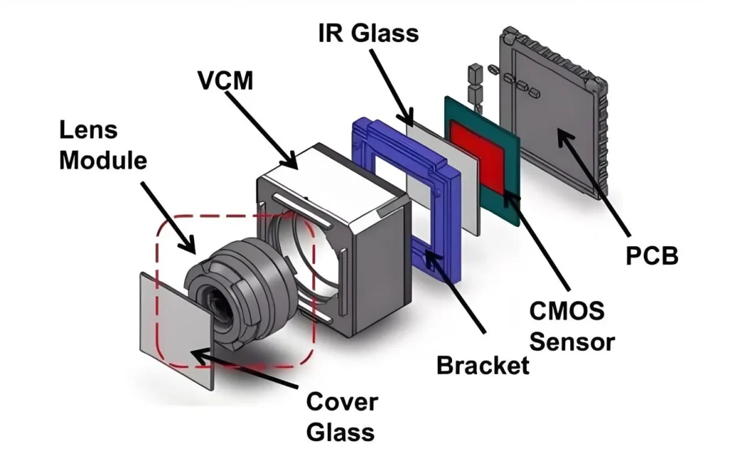
The correct conclusion is not that every front window shifts camera focus. It is that the effect must be assessed using the actual object distance, optical geometry, and field of view.
A Window Between the Lens and Image Sensor
A window in image space is a particularly important case because the rays are usually converging toward the detector.
Examples include camera sensor cover glass, protective detector windows, and additional optical plates inserted into an imaging assembly.
If the lens was designed to focus through a particular cover-glass thickness, removing that glass or replacing it with a different thickness can change the required lens-to-sensor spacing.
Adding another plate without allowing for its optical effect may cause the focused image to move away from the fixed sensor plane.
High-resolution imaging systems may therefore require the cover-glass stack to be considered as part of the lens and sensor optical design, rather than as an independent mechanical accessory.
How to Calculate Optical Window Focus Shift
For an ideal plane-parallel plate inserted perpendicular to the optical axis into a paraxial converging beam, with air on both sides, the approximate axial focus shift is:
Δz ≈ t × (1 − 1/n)
Where:
- Δz = axial focus shift
- t = physical thickness of the window
- n = refractive index of the window material at the operating wavelength
The expression assumes the plate replaces the same axial thickness of air. It also assumes small ray angles, homogeneous material, parallel surfaces, and negligible additional optical effects.
For a converging beam traveling from the lens toward the sensor, the new paraxial focal position is farther downstream than the original air-only focal position.
Example: A 1 mm Glass Window
Suppose a camera optical assembly originally contains only air between a focusing lens and its sensor.
An additional plane-parallel window is introduced with the following illustrative properties:
| Parameter | Value |
|---|---|
| Window thickness | 1.00 mm |
| Refractive index | 1.50 |
| Surrounding medium | Air |
| Window orientation | Normal to the optical axis |
Using the paraxial expression:
Δz ≈ 1.00 × (1 − 1/1.50)
Δz ≈ 0.333 mm
The predicted paraxial focus shift is approximately 0.33 mm toward the sensor side of the optical path.
This is a theoretical calculation, not a measured GIAI optical window specification.
Whether 0.33 mm produces visible blur depends on the lens, aperture, pixel size, wavelength, depth of focus, and available focusing adjustment.
The calculation should not be interpreted as a universal camera performance limit.
What Happens if the Window Thickness Changes?
For the same refractive index and paraxial assumptions, the change in focus shift can be estimated from the change in window thickness:
Δ(Δz) ≈ Δt × (1 − 1/n)
For example, increasing the thickness from 0.50 mm to 1.00 mm gives:
Δt = 0.50 mm
Δ(Δz) ≈ 0.50 × (1 − 1/1.50)
Additional paraxial focus shift ≈ 0.167 mm
This illustrates why changing the thickness of a sensor cover glass or protective window can matter even when both components are made from the same material.
If the replacement also changes the refractive index, each window must be evaluated using its own material properties.
Why the Formula Is Not Enough for Fast Lenses
The expression above describes paraxial rays. It is not a complete prediction of image quality.
For larger ray angles, Snell’s law must be applied without the small-angle approximation.
Let θ be the incident ray angle in air relative to the window normal. The refracted angle inside the window is:
θg = arcsin(sin θ / n)
The corresponding longitudinal intersection shift for that ray is:
Δz(θ) = t × [1 − tan θg / tan θ]
This expression applies to the stated simple geometry: a parallel plate perpendicular to the optical axis, surrounded by air, with the ray in a converging beam.
Different incident ray angles do not generally produce identical intersection shifts.
That difference leads directly to the next problem: aberration.
Why Refocusing May Not Restore the Original Image Quality
Axial focus shift is only one part of the optical behavior of a window.
A camera can sometimes recover satisfactory sharpness simply by adjusting the focus position. In other systems, moving the lens or sensor does not fully restore the original image quality.
The difference is whether the new window produces only a manageable image-plane displacement or also adds significant aberration.
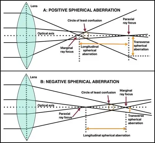
Spherical Aberration in a Converging Beam
In an ideal imaging system, rays from a single object point should converge to the intended image point within the design’s aberration limits.
A plane-parallel plate in a converging beam refracts rays according to their incident angles.
Paraxial rays and marginal rays therefore experience different longitudinal shifts.
As the angular cone becomes wider, the difference can become more significant. The resulting spherical aberration spreads the image energy and can reduce fine-detail contrast.
This is particularly relevant in systems with:
- High numerical aperture
- Small f-number
- Thick transmissive plates in the converging beam
- Tight image-quality requirements
- Optical designs optimized for a specific cover-glass thickness
A useful practical distinction is that defocus can be compensated by repositioning the image plane, while spherical aberration generally cannot be eliminated by a simple focus adjustment.
The full response should be evaluated using the actual optical prescription or a suitable imaging test.
The Microscope Coverslip Example
Microscope objectives demonstrate why a seemingly thin glass plate can matter.
Many microscope objectives are designed for a specified cover-glass thickness, commonly 0.17 mm for objectives intended to operate with a coverslip.
High-numerical-aperture objectives can become sensitive to deviations from their intended cover-glass conditions.
Some objectives use correction collars to compensate for changes in cover-glass thickness or related imaging conditions.
The engineering lesson extends to industrial imaging: the sensitivity is governed by the complete optical design, not by the window thickness alone.
A glass plate that is acceptable for a low-NA imaging system may not be interchangeable with another plate in a high-NA system.
Tilt, Field Angle, and Image Asymmetry
A window that is tilted relative to the nominal optical axis can introduce effects beyond the normal-incidence focus shift.
In a tilted converging beam, different ray paths encounter different incidence conditions. Astigmatism, coma-like contributions, lateral displacement, and other field-dependent effects may become relevant.
For a parallel plate, the emergent ray remains parallel to the incident ray in a uniform surrounding medium, but its lateral position changes.
For a wedged window, the emergent ray may also change direction.
These effects can appear as changes in image position, asymmetric blur, or reduced sharpness across the field.
A system with good central focus but degraded corner performance should not automatically be diagnosed as having a simple axial focus error.
Other Window Problems That Can Look Like Defocus
Not every image that becomes less sharp after adding a window has an axial focus problem.
Several other optical mechanisms can produce similar symptoms.
| Observed symptom | Possible cause | Useful diagnostic |
|---|---|---|
| Image becomes uniformly softer | Axial focus shift or spherical aberration | Perform a focus sweep and compare the best achievable sharpness |
| Center becomes sharp but corners remain soft | Off-axis aberration, tilt, or field-dependent effects | Compare image quality across the full field |
| Bright objects develop faint secondary outlines | Ghost reflections between optical surfaces | Change illumination or window orientation and observe the reflections |
| Contrast drops without a clear change in best-focus position | Scatter, surface contamination, or unwanted reflections | Inspect and clean the window; compare with the uncoated or original configuration |
| Sharpness changes after installation torque is adjusted | Mount-induced deformation or stress | Repeat imaging with controlled mounting conditions |
| Focus changes between different wavelengths | Refractive-index dispersion or chromatic effects | Test at representative operating wavelengths |
Transmitted Wavefront Error
Surface flatness alone does not describe the entire optical effect of a window.
Transmitted wavefront error describes how the wavefront changes after passing through the complete component.
It can be affected by surface-form errors, material inhomogeneity, and stress caused by mounting.
In demanding imaging or measurement systems, transmitted wavefront performance may be more useful than specifying individual surface flatness alone.
The required measurement wavelength, clear aperture, and test conditions should be defined before an acceptance limit is selected.
Ghost Reflections and Coating Performance
A transparent window also introduces additional optical interfaces.
These surfaces may generate reflections that reduce contrast or create ghost images, particularly when strong light sources or reflective sensor surfaces are present.
An anti-reflection coating can reduce unwanted surface reflections over its specified wavelength and angular range.
However, AR coating does not remove the geometric focus shift caused by replacing air with a refractive material.
Coating design and focus compensation solve different optical problems. Both may need attention in the same camera assembly.
How to Troubleshoot a Camera After Installing an Optical Window
When image quality changes after an optical window is installed, isolate the cause before changing the lens, sensor spacing, or component specification.
Step 1: Establish a Baseline
Record the system performance before the window is installed, or compare it against the intended design condition.
Use a stable test target, controlled illumination, fixed working distance, and the same exposure and aperture settings.
Record the focus setting and image sharpness at the center and representative off-axis field positions.
If a production system already includes a sensor cover glass, treat that existing glass as part of the baseline configuration.
Step 2: Determine the Window’s Actual Position
Identify whether the window is located before the imaging lens, inside the lens assembly, or between the lens and sensor.
Also document its distance from nearby optical elements, nominal incidence angle, thickness, material, and mounting orientation.
This step helps establish whether a simple converging-beam focus-shift model is appropriate.
Step 3: Perform a Controlled Focus Sweep
Adjust focus through a sufficient range while keeping the remaining imaging conditions stable.
If the best achievable image quality returns close to the baseline after an axial adjustment, focus shift may be the primary issue.
If the optimum focus position changes but peak image quality remains degraded, additional aberration or other optical effects may be present.
For high-resolution systems, a focus sweep combined with MTF or a repeatable sharpness metric is preferable to relying only on visual inspection.
Step 4: Compare On-Axis and Off-Axis Performance
Evaluate sharpness at the center and near the field edges.
A uniform focus displacement behaves differently from field-dependent aberration, alignment error, or deformation caused by mounting.
If a window is intentionally tilted, test the system in its actual installed orientation rather than only at normal incidence.
Step 5: Check Material, Coating, and Mounting
Confirm the actual material grade, physical thickness, surface condition, and coating requirements.
Inspect for contamination, scratches, ghost reflections, and mounting stress.
Do not assume that changing to an AR-coated window will correct a focus error.
Similarly, tightening a window’s flatness tolerance does not necessarily resolve an image-plane position mismatch.
Step 6: Validate the Corrective Action
Possible corrective measures include adjusting the lens-to-sensor separation, refocusing the lens, using the intended cover-glass thickness, modifying the window location, or redesigning the optics to account for the plate.
The appropriate action depends on the system’s mechanical adjustment range and optical sensitivity.
After any modification, verify performance across the intended working distances, field positions, aperture settings, and operating wavelengths.
A successful central refocus does not by itself demonstrate that the complete imaging system meets its original performance requirements.
What Should Engineers Specify for a Camera Optical Window?
An optical window used in an imaging system should be specified according to its functional position in the optical path.
The following inputs are particularly useful when evaluating whether the window may affect focus or image quality.
| Parameter | Why it matters |
|---|---|
| Window position | Determines whether the beam is collimated, converging, or diverging |
| Material and refractive index | Influence refraction, focus shift, and chromatic behavior |
| Thickness and tolerance | Control the amount and variation of optical path displacement |
| Operating wavelength range | Determines relevant refractive-index values and coating requirements |
| Lens f-number or numerical aperture | Indicates sensitivity to cone-angle-dependent effects |
| Field of view and incidence angles | Help evaluate off-axis aberrations and lateral displacement |
| Parallelism or designed wedge | Influence beam displacement, direction, and unwanted reflections |
| Transmitted wavefront requirement | Relates directly to image-quality-sensitive transmission |
| Clear aperture | Defines the optical region that must meet the specified performance |
| AR coating | Controls reflections and transmission under defined spectral and angular conditions |
| Mounting method and environment | Can influence stress, deformation, and stability |
| Inspection and acceptance method | Establishes how compliance will be verified |
Not every camera window requires the tightest possible optical tolerances.
For some industrial camera enclosures, mechanical protection, environmental resistance, and reflection control may dominate the design.
For high-resolution imaging systems, transmitted wavefront, thickness, orientation, and interactions with the lens prescription may need more attention.
The correct specification follows from the optical function and verified system-level requirements, not from choosing the most demanding component tolerances by default.
For broader drawing and purchasing requirements, see GIAI’s How to Specify a Custom Optical Window engineering guide.
Evaluating Custom Optical Windows for Imaging Systems
When evaluating a custom window, the central question is whether the component will preserve the required optical performance after integration.
GIAI Photonics supports custom optical windows as part of its precision optical component product range.
Custom projects are reviewed against drawings, samples, materials, geometry, optical requirements, coating conditions, and inspection criteria. The manufacturing route is determined by the actual component and project requirements.
For imaging applications, useful inputs include the window position, working wavelength, thickness, refractive index or substrate grade, incidence angle, clear aperture, transmitted wavefront requirement where relevant, and intended optical assembly.
Component inspection and system-level image verification serve different purposes. A window may conform to its drawing while the complete camera still requires focus compensation or further optical optimization.
GIAI’s Quality Assurance information describes the project-specific approach to optical component inspection and acceptance.
Engineers preparing a new window design or reviewing a change to an existing component can submit a drawing, specification, or sample through the GIAI Photonics contact page for project-level feasibility evaluation.
Frequently Asked Questions
Does an optical window always change camera focus?
No. The effect depends on where the window sits and the geometry of the light passing through it. An ideal, normally oriented plane-parallel window in a collimated on-axis beam does not introduce the same axial focus shift as a plate inserted into a converging image-space beam. A window already included in the lens design may also have its effect compensated.
Does a thicker optical window produce more focus shift?
Under the same paraxial conditions and refractive index, the axial focus shift increases approximately in proportion to thickness. In a converging beam surrounded by air, the approximation is Δz ≈ t(1 − 1/n). The relationship does not fully describe high-NA aberrations or tilted-window configurations, which require additional optical analysis.
Can an AR coating prevent optical window focus shift?
No. AR coating is primarily intended to control optical reflections and transmission within a specified spectral and angular range. The underlying geometric focus shift is caused by refraction through the window material. An AR coating may improve contrast and reduce ghost reflections, but it is not a substitute for compensating the window’s optical path effect.
Is focus adjustment enough after adding a protective window?
Sometimes. If the dominant change is a simple axial image-plane displacement and the lens has adequate adjustment range, refocusing may restore acceptable performance. If the window also introduces significant spherical aberration, field-dependent degradation, or transmitted wavefront errors, refocusing alone may not recover the original image quality.
Should an imaging window be specified by surface flatness or transmitted wavefront error?
The appropriate specification depends on the system. Surface flatness describes an individual surface, while transmitted wavefront error evaluates the optical effect of transmission through the component. For wavefront-sensitive imaging systems, transmitted wavefront performance may be more directly relevant. The drawing should identify the required characteristic, test aperture, wavelength, and acceptance conditions.
Engineering Takeaway
An optical window can change camera focus even though it has no conventional focusing power.
In a converging beam, the refraction through a plane-parallel plate shifts the paraxial focal position. In faster or more demanding imaging systems, angle-dependent refraction can also introduce aberrations that cannot be removed by simply adjusting focus.
The most reliable approach is to evaluate the window as part of the complete optical system.
Window thickness, refractive index, beam geometry, lens numerical aperture, mounting conditions, and image-quality requirements should be considered together before the component is finalized.
References
- Wyant, J. C., and Creath, K. Basic Wavefront Aberration Theory for Optical Metrology. Applied Optics and Optical Engineering, Volume XI, Section XI: Aberrations Introduced by Plane Parallel Plates. University of Arizona Optical Sciences reference.
https://wp.optics.arizona.edu/jcwyant/wp-content/uploads/sites/13/2016/08/03-BasicAberrations_and_Optical_Testing.pdf - Edmund Optics. Prism Tunnel Diagrams. Discussion of reduced distance and image displacement through a plane-parallel plate.
https://www.edmundoptics.com/knowledge-center/application-notes/optics/prism-tunnel-diagrams/ - Edmund Optics. Understanding Optical Windows. Material properties, transmitted wavefront error, optical coatings, and window selection.
https://www.edmundoptics.com/knowledge-center/application-notes/optics/understanding-optical-windows/ - Nikon MicroscopyU. Coverslip Correction Collars. Explanation of objective sensitivity to coverslip thickness and related aberrations.
https://www.microscopyu.com/tutorials/slipcorrection