
Technical Resources
Wedged vs Parallel Optical Windows: Ghost Reflections
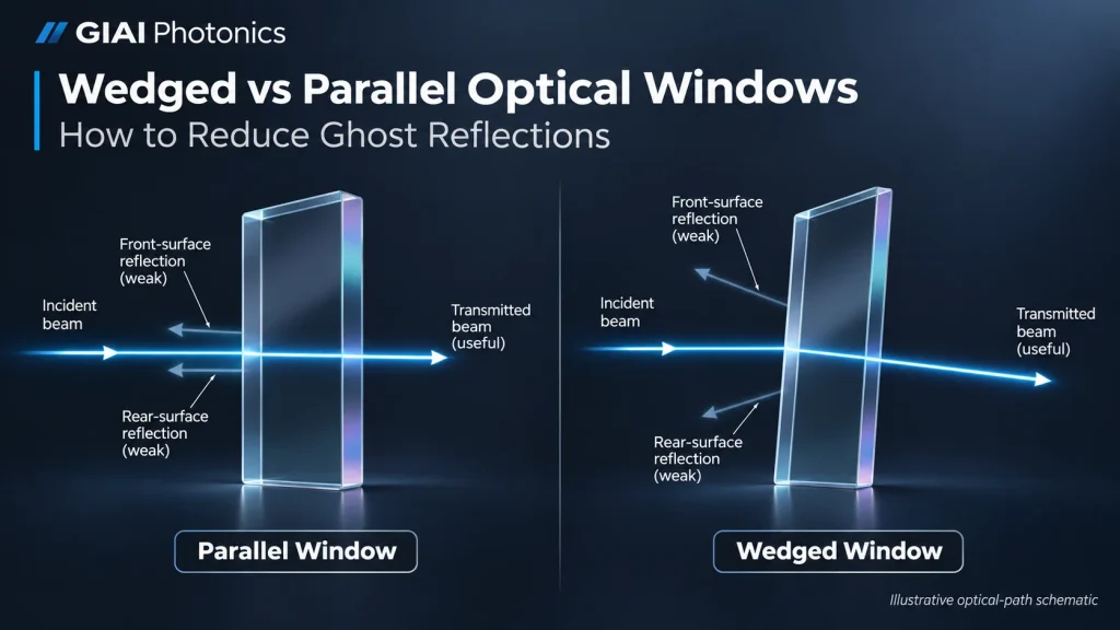
An optical window is often treated as one of the simplest components in an optical system. It has no intended focusing power, and its primary function is usually to transmit light while protecting or separating sensitive components.
Yet a window can introduce problems that are difficult to trace: unwanted reflections, interference fringes, laser feedback, ghost images, or changes in beam direction.
One important design decision is whether the window should have parallel surfaces or an intentional wedge.
A parallel optical window maintains the transmitted beam direction in a uniform surrounding medium, although it may introduce lateral displacement at oblique incidence. A wedged optical window has a controlled angle between its surfaces, helping separate unwanted reflections and reduce etalon-related interference. However, the wedge also introduces beam deviation.
Neither design is universally better. The correct choice depends on the optical layout, source coherence, reflection sensitivity, wavelength, coating, and alignment requirements.
Wedged vs Parallel Optical Windows: Key Differences
Both components can be used for optical transmission and environmental protection. Their defining difference is the relative orientation of the two optical surfaces.
A parallel window has nominally parallel entrance and exit faces. A wedged window deliberately introduces a small angular difference between those faces.
This geometry changes how the transmitted beam and secondary reflected beams propagate through the system.
| Parameter | Parallel Optical Window | Wedged Optical Window |
|---|---|---|
| Surface geometry | Two nominally parallel faces | Two faces separated by a controlled wedge angle |
| Transmitted beam direction | No net angular deviation in a uniform surrounding medium | Small angular deviation |
| Lateral beam displacement | Possible at oblique incidence | Depends on thickness, incidence, wedge, and orientation |
| Secondary reflections | Can remain parallel and overlap | Can be separated angularly |
| Etalon effects | Possible when coherent reflected beams overlap | Often reduced through angular separation and varying optical thickness |
| Laser feedback | May require window tilt or other mitigation | Can help redirect secondary reflections, subject to orientation |
| Imaging considerations | Useful where beam pointing must be preserved | May require compensation for beam steering and dispersion |
| Key specification | Parallelism tolerance | Nominal wedge angle, tolerance, and orientation |
The distinction is particularly important in laser systems, interferometers, spectroscopy equipment, and optical instruments where even relatively weak unwanted reflections can affect measurement stability.
Why Can an Optical Window Create Ghost Reflections?
Whenever light crosses an interface between materials with different refractive indices, part of the incident optical power may be reflected.
For an uncoated glass window surrounded by air, reflections occur at both the entrance and exit surfaces.
The exact reflected fraction depends on refractive index, angle of incidence, and polarization. At near-normal incidence, a typical uncoated air–glass interface can reflect several percent of the incident optical power.
An anti-reflection (AR) coating can reduce this reflection over its specified wavelength and angular range, but does not necessarily eliminate it.
Consider a laser beam passing through a parallel optical window.
At the first surface, a fraction of the beam reflects backward. The transmitted portion travels through the substrate, reaches the second surface, and experiences another partial reflection.
Part of this second reflection returns through the window and can emerge toward the source.
For a parallel window near normal incidence, these reflected beams may travel in nearly the same direction. Depending on the optical geometry, they can overlap with the input beam or with one another.
These secondary paths become particularly important when the optical system is sensitive to coherent feedback or interference.
Ghost reflections in imaging systems
In an imaging system, unwanted reflections can form secondary light paths that reach the sensor.
Depending on the spacing, curvature of adjacent components, aperture, and detector geometry, these paths may produce faint displaced images, glare, or background artifacts.
A protective window can contribute to such artifacts, but it is rarely the only possible source. Lens surfaces, detector covers, beam splitters, and other interfaces may also generate unwanted reflections.
An intentional wedge may help move certain ghost reflections away from the useful optical path. Whether that separation is sufficient depends on the complete system geometry.
Back reflections in laser systems
Laser systems introduce another concern: optical feedback.
Light reflected toward a laser source may re-enter the laser cavity or otherwise interact with the source.
Depending on the laser architecture and feedback level, this can contribute to intensity fluctuations, frequency instability, or other unwanted behavior.
A wedged window is one possible method for changing the directions of secondary reflections. However, a wedge is not a substitute for a properly designed optical isolation strategy when significant feedback suppression is required.
How Do Parallel Windows Produce Etalon Effects?
A parallel optical window can behave as a weak Fabry–Pérot etalon.
An etalon consists of two partially reflecting surfaces separated by an optical path. Multiple reflected and transmitted waves can interfere when their coherence and spatial overlap are sufficient.
In a parallel window, the optical thickness between the faces is approximately uniform across the aperture.
Under suitable illumination conditions, multiple transmitted components acquire phase differences that can produce wavelength-dependent intensity modulation.
This effect may appear as unwanted spectral fringes, intensity variations, or systematic errors in optical measurements.
Its significance depends on several variables:
- Source coherence: A narrow-linewidth laser is generally more susceptible to coherent interference than a sufficiently broadband, low-coherence source.
- Surface reflectance: Stronger internal reflections can increase interference contrast.
- Window thickness and refractive index: These determine the optical path between successive internal reflections.
- Angle of incidence: The optical path and overlap geometry change with incidence angle.
- Beam diameter and angular distribution: These influence whether the reflected components overlap and interfere.
- Measurement sensitivity: A modulation that is negligible in one system may be unacceptable in a precision instrument.
An etalon is not inherently undesirable. Deliberately designed Fabry–Pérot devices are useful for spectral selection and interferometric measurements.
The problem occurs when a window unintentionally introduces etalon behavior into a system that was not designed to accommodate it.
For example, unwanted optical resonances, sometimes called channeling, can affect Fourier-transform infrared spectrometers. Research published in Atmospheric Measurement Techniques discusses how wedged components and component tilt can reduce these effects, while also identifying practical limitations.
How Does a Wedged Optical Window Reduce Unwanted Reflections?
A wedged window changes the angle between the entrance and exit surfaces.
Consequently, reflected beams from the two surfaces do not necessarily propagate along parallel or coincident paths.
The difference in propagation direction can help separate secondary reflections spatially or angularly from the main beam.
This is one reason wedged windows are used in reflection-sensitive optical systems.
The wedge also causes the substrate thickness to vary across the aperture. This changes the phase relationship between internal reflections across the illuminated region, which can reduce the net interference observed by the system.
These effects are related but distinct.
Angular separation redirects unwanted reflected beams. Reduced etalon interference results from changes in the overlap and phase relationships of those beams.
A wedge does not directly remove the Fresnel reflection at either surface.
Why the wedge angle matters
A small wedge may be enough to separate reflected beams in one optical layout but insufficient in another.
A larger wedge generally increases angular separation, but also increases deviation of the transmitted beam.
The required wedge therefore depends on the optical system rather than a universal recommended angle.
A peer-reviewed study by C. Ai and J. C. Wyant, published in Applied Optics in 1993, investigated the influence of multiple reflections when testing optical windows with small wedge angles.
The study demonstrated that a very small wedge does not necessarily remove the resulting measurement errors. Appropriate alignment of the window and the return mirror can also be important.
This illustrates a practical design principle: adding a wedge does not automatically guarantee that ghost reflections or interference artifacts become negligible.
What about the first-surface reflection?
An important limitation is sometimes overlooked.
Suppose a laser beam strikes the first surface of a wedged window at normal incidence.
That first surface still produces a reflection directed back along the incident path, even though the opposite surface is tilted relative to it.
The wedge changes the rear-surface reflection geometry, but does not eliminate this initial reflection.
If suppression of direct optical feedback is required, the engineer must consider the window’s installed tilt, AR coating, and other feedback-control measures.
The relevant quantity is not merely the wedge angle printed on the drawing. It is the direction and power of every significant reflected beam in the assembled system.
Does a Wedged Window Change the Transmitted Beam Direction?
Yes.
A wedged window behaves as a weak prism.
Because the two refracting surfaces are not parallel, their angular effects do not cancel in the same way as those of an ideal plane-parallel plate.
For a small wedge angle and near-normal incidence in air, the approximate angular deviation is:
[
\delta \approx (n-1)\alpha
]
Where:
- (\delta) is the transmitted beam deviation angle.
- (n) is the refractive index of the window material relative to air.
- (\alpha) is the wedge angle between the surfaces.
The small-angle approximation assumes consistent angular units and is most useful for preliminary estimates. Exact ray tracing is appropriate when incidence angles, precision requirements, or system geometry demand it.
Illustrative calculation
Consider a hypothetical optical window with:
- Refractive index: (n=1.46)
- Wedge angle: (\alpha=0.5^\circ)
- Beam entering approximately normal to the first surface
- Air surrounding the window
The estimated transmitted beam deviation is:
[
\delta \approx (1.46-1)\times0.5^\circ
]
[
\delta \approx 0.23^\circ
]
This is an illustrative optical calculation, not a GIAI product specification or measured result.
Although the deviation may appear small, it can produce a meaningful beam-position difference after propagation over a substantial distance.
The resulting alignment impact depends on the location of the window, beam geometry, downstream optics, and mechanical tolerances.
Wavelength dependence
Refractive index changes with wavelength.
Consequently, the angular deviation introduced by a wedged window can also vary with wavelength.
For broadband systems, this prism-like dispersion may be relevant to image registration, beam positioning, or chromatic performance.
The effect should be evaluated against the actual spectral range and optical layout rather than judged from a single-wavelength calculation.
When Should You Choose a Parallel Optical Window?
A parallel window is often appropriate when the system benefits from maintaining the incident beam direction.
Examples include protective windows in imaging systems, optical sensors, and precision instruments where beam steering would complicate alignment.
In an ideal plane-parallel window surrounded by the same optical medium on both sides, the outgoing ray is parallel to the incident ray.
At nonzero incidence, the transmitted ray is laterally displaced. The displacement depends on incidence angle, refractive index, and thickness.
A parallel window may therefore preserve beam direction without preserving the exact original beam position.
For precision imaging, surface form, transmitted wavefront, thickness, mounting stress, and the location of the window within the optical system may be more important than parallelism alone.
A parallel window is often the more straightforward choice when:
- The application is not strongly sensitive to coherent back reflections.
- Minimum angular beam deviation is important.
- The window is used in a geometry where added prism deviation would be undesirable.
- Ghost reflections can be controlled through coatings, positioning, or system design.
- The assembly requires a simple and well-defined optical alignment reference.
However, parallelism should still be specified as a tolerance, not assumed from the term “optical flat.”
Surface flatness and parallelism describe different properties and should not be used interchangeably.
When Is a Wedged Optical Window the Better Choice?
A wedged window becomes attractive when unwanted reflection overlap or parasitic interference is a significant system-level concern.
Potential applications include laser instrumentation, coherent optical measurement systems, interferometric equipment, and certain spectroscopy arrangements.
Its value is not that it has universally better optical quality.
The benefit is that it changes the geometry of unwanted optical paths.
A wedged window may be preferable when:
- Reflections from nominally parallel faces overlap with a sensitive optical path.
- Unwanted etalon fringes affect measurements.
- Secondary reflected beams need to be separated from useful beams.
- The system can accommodate or compensate for transmitted beam deviation.
- The window orientation can be controlled during assembly.
The wedge angle should be selected based on the required reflection separation and the permitted beam-steering error.
A larger angle is not automatically better.
The designer must also evaluate the available clear aperture, coating performance, packaging constraints, and orientation relative to the incident beam.
Can AR Coatings Replace the Need for a Wedged Window?
Not in every application.
AR coatings and wedge geometry address different aspects of unwanted reflections.
An AR coating reduces reflected optical power over a defined wavelength range and angle-of-incidence condition.
A wedge changes the propagation directions and relative phases of reflected components.
These mechanisms can be complementary.
For example, a window with suitable AR coatings may generate weaker secondary reflections, while an intentional wedge can further reduce their overlap with a sensitive optical path.
However, neither measure guarantees complete elimination of unwanted feedback.
When defining an AR-coated window, important specifications include the operating wavelength range, reflectance requirement, angle of incidence, polarization where relevant, and whether one or both faces require coating.
The system’s angular distribution should also be considered. A coating optimized for a single nominal incidence angle may not perform identically across a converging or diverging beam.
For high-power laser applications, additional requirements concerning absorption, thermal behavior, surface condition, and laser-induced damage may be necessary.
Laser damage performance should be verified for the specified wavelength, pulse conditions, and applicable test method. It should not be inferred solely from the presence of an AR coating.
Common Design Mistakes When Selecting Window Geometry
Several recurring specification errors can create avoidable problems during optical-system integration.
| Common Mistake | Why It Matters | Better Engineering Approach |
|---|---|---|
| Assuming every optical window is perfectly parallel | Manufactured windows have finite geometry tolerances | Define the allowable parallelism or intentional wedge |
| Assuming a wedge eliminates all reflections | Fresnel reflections still occur at the interfaces | Evaluate reflected power, direction, and coating performance |
| Selecting the largest available wedge angle | Increased wedge can produce unwanted beam steering | Determine the minimum useful separation for the actual layout |
| Ignoring installed orientation | Wedge direction changes the geometry of reflected and transmitted beams | Define orientation and mechanical datums |
| Treating AR coating as a universal solution | Coating performance depends on wavelength, incidence, and polarization | Specify spectral and angular operating conditions |
| Specifying only surface flatness | Flatness does not independently define transmitted wavefront or wedge | Specify each relevant optical characteristic separately |
| Evaluating the window in isolation | Adjacent optics and detectors determine whether ghosts are harmful | Review the complete optical path |
These mistakes commonly arise when a window is selected as a mechanical protection component without considering its optical influence.
How to Specify a Custom Wedged or Parallel Optical Window
A custom optical window specification should start with system function rather than a nominal component description.
A drawing that states only “optical glass window, AR coated” leaves important design decisions undefined.
The following information provides a practical basis for engineering review.
| Specification | Information to Define |
|---|---|
| Optical function | Protection, transmission, isolation, laser window, imaging window, or other function |
| Wavelength range | Operating wavelength or spectral band |
| Material | Substrate and grade where relevant |
| Geometry | Outside diameter or length and width, thickness, edge features |
| Clear aperture | Region over which optical requirements apply |
| Window type | Parallel or intentionally wedged |
| Wedge / parallelism | Nominal angle and tolerance, or maximum allowed nonparallelism |
| Orientation | Entrance face, wedge direction, reference surfaces, and mounting datums |
| Optical quality | Surface form, transmitted wavefront, surface imperfections where required |
| Coating | Wavelength, reflectance or transmission limits, AOI, polarization, coated faces |
| Reflection management | Permitted return direction, ghost displacement, or feedback limits |
| Environment | Temperature, humidity, vacuum, pressure, cleaning, or other conditions |
| Verification | Measurement method, test aperture, conditions, and acceptance criteria |
| Quantity | Prototype quantity and anticipated production requirements |
International optical drawing conventions, including ISO 10110-1, provide a framework for communicating optical-element requirements and tolerances.
A useful specification should also clarify which characteristics are essential to system performance.
Not every window needs the tightest achievable flatness, parallelism, surface quality, or coating target.
Over-specification can increase manufacturing and inspection complexity without improving the actual optical result.
For broader guidance, see GIAI’s How to Specify a Custom Optical Window.
How should the geometry be verified?
Verification should correspond to the function the window performs in the assembled system.
For a parallel window, the inspection plan may include surface parallelism, transmitted wavefront, dimensions, and the resulting beam deviation under defined test conditions.
For an intentionally wedged window, verification may include the wedge angle, its orientation relative to mechanical datums, and transmitted-beam deviation.
Where ghost suppression is a critical requirement, evaluating the actual reflection geometry can be more meaningful than measuring wedge angle alone.
Reflection tests should use representative wavelength, incidence, beam geometry, and polarization conditions where applicable.
A window can conform to its mechanical drawing while still producing unacceptable ghosts in a particular optical assembly if the system-level reflection requirement was never defined.
Inspection requirements should therefore be established before manufacturing and aligned with the intended acceptance criteria.
Custom Optical Window Engineering Review at GIAI Photonics
GIAI Photonics includes optical windows within its precision optical component and custom optics manufacturing scope.
GIAI’s publicly described manufacturing activities include material preparation, grinding, polishing, geometric processing, optical coating, cleaning, and inspection, as appropriate for the specific component.
For custom optical window projects, the engineering review considers the drawing or sample, substrate, optical function, dimensions, coating requirements, and inspection criteria before defining a manufacturing route.
An intentional wedge, its tolerance, and any associated reflected-beam or transmitted-wavefront requirement must be evaluated for the individual project. They should not be interpreted as universal manufacturing limits or guaranteed performance.
Further information is available in GIAI’s Manufacturing Capabilities and Quality Assurance resources.
For engineering evaluation, provide the available drawing or sample together with the wavelength range, material, geometry, required wedge or parallelism, coating specification, angle of incidence, and inspection requirements.
The objective is to define a window that meets the needs of the optical system—not simply to select the component with the tightest individual specifications.
Frequently Asked Questions
1. What is the main difference between a wedged and a parallel optical window?
A parallel optical window has nominally parallel surfaces and preserves the transmitted beam direction in a uniform surrounding medium, although lateral displacement may occur. A wedged optical window has a controlled angle between its faces, creating a small angular deviation while helping separate secondary reflections. The correct geometry depends on acceptable beam deviation, unwanted reflection overlap, and system alignment requirements.
2. Does a wedged optical window eliminate ghost reflections?
No. A wedged window changes the directions and phase relationships of secondary reflected beams, which can reduce their overlap and interference. Reflections still occur at the optical interfaces unless reduced by suitable coatings or other measures. The first surface can still reflect light directly toward a laser source if the incident beam is normal to that surface.
3. Can a parallel optical window cause interference fringes?
Yes. Under suitable coherence and alignment conditions, its two partially reflecting surfaces can produce Fabry–Pérot-type interference. The resulting fringes depend on source bandwidth, surface reflectance, optical thickness, incidence angle, and beam overlap. Broad-spectrum or low-coherence illumination may make these effects much less significant in some applications.
4. How much wedge angle is required to prevent etalon effects?
There is no universal minimum wedge angle. The required value depends on wavelength, beam diameter, coherence, optical geometry, reflectance, and measurement sensitivity. Very small wedge angles may be insufficient to suppress interference-related errors. The selected angle must also satisfy the system’s beam-deviation and alignment requirements.
5. Is a wedged window better for laser applications?
It can be useful for laser systems sensitive to coherent feedback or parasitic interference, provided the resulting beam deviation is acceptable. However, a wedged window does not replace optical isolation, correct alignment, or an appropriate coating specification. Its suitability depends on the laser and the complete optical path.
6. Should I specify transmitted wavefront or surface flatness for an optical window?
The answer depends on which optical characteristic controls system performance. Surface flatness describes an individual surface; transmitted wavefront describes the wavefront after passage through the complete component. For wavefront-sensitive imaging, interferometry, or precision beam delivery, transmitted wavefront may be a more direct acceptance requirement. Wedge or parallelism should be specified separately.
Recommended Internal Links
The following GIAI pages are relevant to this technical article:
- Optical Windows — GIAI Photonics — Component family and optical window applications.
- Lenses & Optical Components — Related optical component engineering resources.
- How to Specify a Custom Optical Window — Drawing and specification guidance.
- Manufacturing Capabilities — Public manufacturing and project-review scope.
- Quality Assurance — Inspection criteria and verification approach.
- Contact GIAI Photonics — Submit drawings, samples, or requirements for project review.
Image Plan
Featured Image
Concept: A side-by-side technical comparison showing how light behaves when passing through a parallel optical window versus an intentionally wedged optical window.
Aspect Ratio: 16:9
Suggested Filename: wedged-vs-parallel-optical-windows.webp
ALT Text: Comparison of parallel and wedged optical windows showing transmitted beam direction and secondary reflected light paths.
Featured Image Prompt:
Create a professional 16:9 engineering visualization for GIAI Photonics about “Wedged vs Parallel Optical Windows.”
Show a clean, side-by-side comparison of two transparent precision optical windows within a controlled optical laboratory setting.
On the left, show a plane-parallel optical window with two parallel polished faces, a nearly normal incident laser beam, the transmitted beam, and weak front- and rear-surface reflected rays.
On the right, show a wedged optical window with a clearly visible but modest intentional wedge angle, a transmitted beam with slight angular deviation, and separated secondary reflected paths.
Use physically consistent refraction and reflection geometry. Differentiate the useful transmitted beam from weak parasitic reflections using subtle color and line styling. Avoid depicting infrared radiation as a physically visible beam.
Use dark navy, graphite, transparent glass, restrained blue and cyan optical highlights, and a precise industrial-photonics aesthetic.
Include only two minimal labels: “Parallel Window” and “Wedged Window.”
Do not include invented dimensions, performance measurements, product specifications, or manufacturer logos. Label the visualization as an illustrative optical-path schematic.
Optional In-Body Illustrations
Figure 1 — Surface Reflections in a Parallel Window
Filename: parallel-window-ghost-reflections.webp
Create a clean technical ray diagram showing partial reflection and transmission at both faces of a parallel optical window. Distinguish the first-surface reflection, internally reflected beam, secondary return, and main transmitted beam. Use consistent ray directions and illustrate how reflected paths can overlap. Minimal labels, white background, physically plausible geometry, and no numerical performance claims.
ALT: Ray diagram illustrating ghost reflections from the two faces of a parallel optical window.
Figure 2 — Wedge Angle and Beam Deviation
Filename: optical-window-wedge-angle-beam-deviation.webp
Create a precise optical engineering schematic of a transparent wedged window. Show an incident ray, a refracted ray inside the substrate, the transmitted ray, the wedge angle alpha, and the beam deviation delta. Illustrate a small but clearly visible angular difference. Use clean vector geometry, a light background, and minimal labels. Do not imply measured GIAI performance.
ALT: Optical ray diagram showing wedge angle and transmitted beam deviation through a wedged window.
Figure 3 — Parallel and Wedged Windows in a Laser System
Filename: laser-system-optical-window-reflection-paths.webp
Create a two-panel conceptual laser optical-path diagram. The first panel shows a parallel window with backward reflection paths. The second shows a wedged window with appropriate non-normal mounting, separated return paths, and slight transmitted-beam deviation. Include a generic laser source and a downstream optical detector. Clearly differentiate useful transmission from unwanted feedback. Mark as schematic; no commercial equipment identities or test results.
ALT: Conceptual laser optical system comparing back-reflection paths through parallel and wedged windows.
Technical References
- RP Photonics Encyclopedia, article on “Optical Windows”, Dr. Rüdiger Paschotta.
https://www.rp-photonics.com/optical_windows.html - RP Photonics Encyclopedia, article on “Wedge Prisms”, Dr. Rüdiger Paschotta.
https://www.rp-photonics.com/wedge_prisms.html - Ai, C., and Wyant, J. C. (1993). “Testing an optical window of a small wedge angle: effect of multiple reflections.” Applied Optics, 32(25), 4904–4912.
https://doi.org/10.1364/AO.32.004904 - Atmospheric Measurement Techniques (2021). “Characterization and potential for reducing optical resonances in Fourier transform infrared spectrometers of the Network for the Detection of Atmospheric Composition Change (NDACC).”
https://amt.copernicus.org/articles/14/1239/2021/ - ISO 10110-1:2019. Optics and photonics — Preparation of drawings for optical elements and systems — Part 1: General.
https://www.iso.org/standard/57574.html