
Technical Resources
Polarizing vs Non-Polarizing Beamsplitter
A beamsplitter is often described simply as an optical component that divides one incident beam into transmitted and reflected paths. In an actual optical system, however, an important question comes first:
Should the splitting behavior depend on polarization?
That question separates two major categories: polarizing beamsplitters (PBS) and non-polarizing beamsplitters (NPBS).
A polarizing beamsplitter intentionally separates the orthogonal polarization components of light. A non-polarizing beamsplitter is instead designed so that its transmission and reflection are as similar as practical for s- and p-polarized light over the specified wavelength and angle of incidence.
The distinction matters in laser systems, interferometers, imaging instruments, polarization measurements, fluorescence instruments, optical sensors, and many other systems. Choosing the wrong type can produce an incorrect power ratio, unwanted polarization changes, reduced contrast, or measurement errors.
Polarizing vs Non-Polarizing Beamsplitter at a Glance
| Parameter | Polarizing Beamsplitter | Non-Polarizing Beamsplitter |
|---|---|---|
| Primary function | Separate orthogonal polarization states | Split optical power with reduced polarization dependence |
| Typical behavior | One polarization mainly transmitted, the orthogonal polarization mainly reflected | s and p components designed for similar R/T behavior |
| Dependence on input polarization | Intentionally high | Intentionally minimized |
| Important specification | Extinction ratio | Split ratio and s/p matching |
| Typical use | Polarization separation, analysis, combining | Imaging, interferometry, beam sampling, general power splitting |
| Input state | Usually known or intentionally controlled | Can accommodate varying or unknown polarization more easily |
| Main design concern | Leakage of the unwanted polarization | Difference between s- and p-polarized transmission/reflection |
| Common geometry | Cube or prism-based | Plate or cube |
| AOI sensitivity | Must be specified | Must also be specified |
| Coating requirement | Polarization-selective coating | Coating designed to minimize s/p difference |
The important point is that “polarizing” and “non-polarizing” describe the intended optical behavior, not simply the mechanical shape of the component. Either category may use a cube, plate, prism, or another coated optical geometry depending on the design.
What Is a Polarizing Beamsplitter?
Any incident beam can be resolved into two orthogonal linear polarization components relative to the plane of incidence:
- s-polarized light, with the electric field perpendicular to the plane of incidence;
- p-polarized light, with the electric field parallel to the plane of incidence.
A polarizing beamsplitter deliberately gives these two components very different reflection and transmission characteristics.
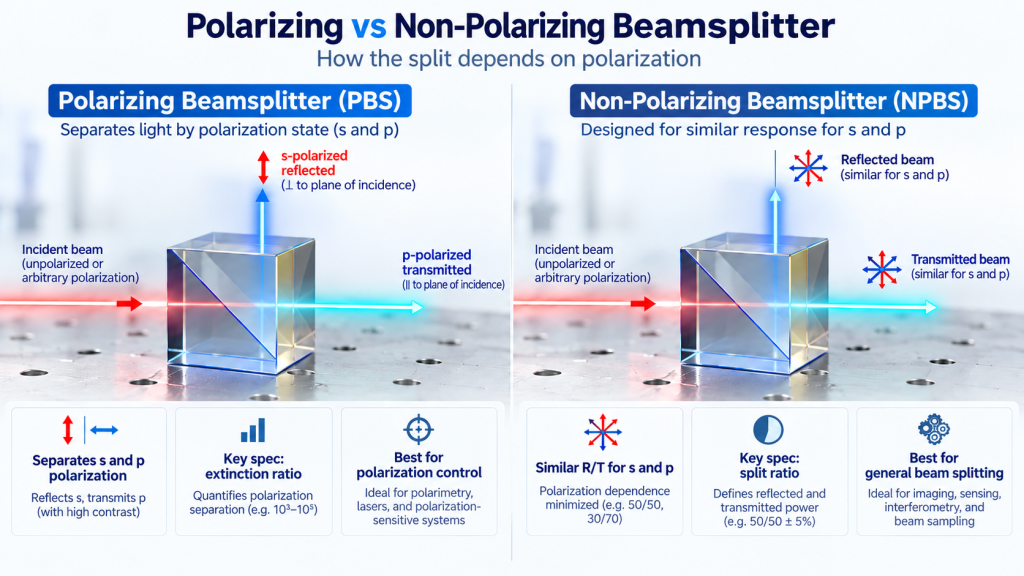
A common PBS cube configuration is designed so that p-polarized light is predominantly transmitted while s-polarized light is predominantly reflected. Commercial PBS designs commonly use this arrangement, although engineers should always check the actual coating specification and port definition rather than assuming the same convention for every component.
In simplified form:
for the transmitted port, while:
for the reflected port.
This allows one incoming beam to produce two output beams with substantially different polarization states.
The key PBS parameter: extinction ratio
For a polarizing beamsplitter, a nominal transmission percentage alone is not enough. Engineers often need to know how much unwanted polarization leaks into the selected output.
For the transmitted p-polarized output, an extinction ratio may be expressed as:
while a reflected-port specification may instead compare the reflected s and p components.
A higher extinction ratio means better separation between the desired and unwanted polarization components. The two output ports do not necessarily have identical extinction performance, so the relevant port should be specified when evaluating a PBS.
What Is a Non-Polarizing Beamsplitter?
A non-polarizing beamsplitter has a different objective. Rather than separating s and p polarization, its coating is designed to make the two polarization components behave as similarly as possible.
For an idealized 50:50 NPBS:
and
with approximately half of the optical power directed into each path.
Real optical coatings are not perfectly polarization-independent. At oblique incidence, Fresnel behavior is inherently different for s and p polarization, so the coating designer must compensate for that difference over a defined wavelength range and AOI.
For this reason, “non-polarizing” should not be interpreted as “polarization has absolutely no effect.” It means the optic has been designed to reduce polarization-dependent variation to a specified level.
For example, commercial NPBS specifications may explicitly define the permitted difference between s- and p-polarized transmission or reflection. This illustrates why an engineer should look beyond the words “50/50 non-polarizing” and inspect the actual s/p tolerance.
The Fundamental Difference Is the Treatment of s and p Polarization
Suppose an incident beam contains both polarization components:
The reflected optical power can be approximated as:
and the transmitted optical power as:
For a PBS, the coating intentionally makes , , , and very different.
For an NPBS, the objective is approximately:
and:
This difference explains an important practical effect.
If a nominal 50:50 beamsplitter has significant polarization dependence, rotating the polarization direction of the incident laser can change the measured output ratio. In a polarization-insensitive imaging or measurement system, that may be undesirable.
In a polarization-control system, by contrast, that same sensitivity is exactly what the engineer wants from a PBS.
50:50 Does Not Automatically Mean Non-Polarizing
One of the most common specification mistakes is assuming that any beamsplitter described as 50:50 is also non-polarizing.
These are separate requirements.
“50:50” describes the intended optical power division under specified test conditions. It does not automatically define how the component behaves for different polarization states.
A more complete specification might therefore define:
- operating wavelength or wavelength range;
- angle of incidence;
- and ;
- and ;
- average R:T ratio;
- permitted s/p mismatch;
- polarization state used during verification.
This is particularly important for laser systems because the input beam may already be strongly linearly polarized.
Why Angle of Incidence Matters
Polarization behavior and AOI are closely connected.
At normal incidence, the distinction between s and p polarization with respect to the interface effectively disappears. At oblique incidence, their Fresnel reflection coefficients diverge.
Many plate and cube beamsplitters therefore rely on a coating designed for a specific AOI, frequently around an oblique working geometry such as 45°.
Changing the actual AOI can alter:
- reflection;
- transmission;
- R:T split ratio;
- s/p matching;
- extinction ratio;
- spectral response.
Commercial non-polarizing beamsplitters, for example, are normally specified with a defined wavelength and AOI rather than being described as polarization-independent under every possible condition.
Consequently, AOI should be part of the beamsplitter specification rather than treated as only a mechanical mounting detail.
Wavelength Range Is Equally Important
Multilayer beamsplitter coatings are wavelength-dependent.
A coating optimized for one laser wavelength may behave very differently several hundred nanometers away. Broadband designs are possible, but maintaining both the desired splitting ratio and low polarization sensitivity across a wide spectral range becomes more demanding.
The engineering trade-off is therefore not simply:
PBS or NPBS?
It is more accurately:
PBS or NPBS at what wavelength range, AOI, polarization state, and required splitting accuracy?
Some broadband non-polarizing designs deliberately accept looser R:T accuracy or some optical absorption to achieve lower polarization sensitivity across a broader wavelength range. Commercial specifications illustrate this trade-off directly.
Polarizing vs Non-Polarizing Beamsplitter: Which Should You Use?
Choose a polarizing beamsplitter when polarization separation is part of the optical function
A PBS is normally the more appropriate starting point when the system needs to:
- separate s and p polarization;
- analyze polarization state;
- combine two orthogonally polarized beams;
- route optical power according to polarization;
- work with polarization modulators;
- construct polarization-sensitive measurement paths.
Here, extinction ratio and polarization leakage usually matter more than achieving an identical power split for arbitrary input polarization.
Choose a non-polarizing beamsplitter when power division should remain relatively stable with polarization
An NPBS is generally more suitable when the system needs to:
- divide an imaging path;
- send part of a beam to a reference detector;
- create measurement and monitoring channels;
- split light in an interferometer;
- work with unknown or changing polarization;
- reduce output-power variation caused by input polarization changes.
Here, the engineer usually pays closer attention to the R:T ratio and the difference between s- and p-polarized response.
PBS vs NPBS in Imaging Systems
In an imaging system, unwanted polarization dependence can produce different intensities depending on the polarization introduced by the source, mirrors, windows, coatings, or sample.
An NPBS is therefore often considered when the objective is simply to create two imaging paths without intentionally analyzing polarization.
But “non-polarizing” alone does not guarantee identical images in both ports.
Other properties may also matter:
- transmitted wavefront;
- reflected wavefront;
- surface flatness;
- substrate quality;
- coating uniformity;
- clear aperture;
- ghost reflections;
- wedge;
- chromatic behavior.
For precision imaging, these properties may become just as important as the nominal beamsplitting ratio.
Cube vs Plate Beamsplitters
Both PBS and NPBS designs can use different mechanical forms.
Cube beamsplitter
A cube is commonly formed from two prisms with the beamsplitting interface inside the assembly.
Advantages can include a compact geometry and convenient approximately 90° separation between transmitted and reflected paths.
The application may nevertheless need to consider:
- internal coating characteristics;
- optical path length;
- adhesive or optical-contact construction where applicable;
- thermal behavior;
- wavefront requirements;
- laser power or pulse conditions.
Plate beamsplitter
A plate beamsplitter uses a coated planar substrate.
It can be attractive when low mass, simple mounting, or certain laser-system requirements are important. However, the second surface can generate unwanted reflections or ghost beams.
For this reason, plate designs may use a wedged substrate and an AR coating on the rear surface to spatially separate or suppress unwanted secondary reflections. This approach is used in commercial non-polarizing plate beamsplitters.
Therefore, PBS vs NPBS and cube vs plate are two different design decisions.
Do Non-Polarizing Beamsplitters Preserve Polarization?
Not necessarily.
This is an important distinction.
An NPBS is normally designed to reduce differences in amplitude response between s and p components. A polarization-sensitive system may also care about the relative phase shift introduced between those components.
Consequently, a component can have similar and values while still altering the state of polarization because the reflected or transmitted s and p components accumulate different phase shifts.
If downstream performance depends on:
- linear polarization orientation;
- circular polarization;
- ellipticity;
- retardance;
- interferometric phase;
then amplitude specifications alone may be insufficient.
The coating phase response should be considered as part of the optical-system analysis.
Specifications to Define Before Ordering
For a polarizing or non-polarizing beamsplitter, it is useful to define the optical requirement before selecting a coating.
Typical project inputs include:
Optical requirements
- wavelength or wavelength range;
- nominal R:T ratio;
- angle of incidence;
- input polarization;
- required behavior;
- extinction ratio for PBS applications;
- acceptable polarization dependence for NPBS applications.
Mechanical requirements
- cube, plate, prism, or other geometry;
- dimensions;
- thickness;
- clear aperture;
- mounting constraints.
Optical quality
- transmitted wavefront requirement;
- reflected wavefront requirement;
- surface quality;
- flatness where relevant;
- allowable wedge or beam deviation.
Application conditions
- CW or pulsed source;
- optical power or pulse conditions;
- operating environment;
- imaging or non-imaging use;
- required inspection method and documentation.
This is preferable to requesting only a “50/50 beamsplitter,” because the same nominal power ratio may correspond to substantially different optical behavior in the final system.
Polarizing vs Non-Polarizing Beamsplitter: The Selection Rule
The simplest decision rule is:
Use a polarizing beamsplitter when polarization itself is the signal you want to separate or control.
Use a non-polarizing beamsplitter when you want the beam division to depend as little as practical on polarization.
After that first decision, specify the conditions that determine whether the component will actually work:
wavelength + AOI + polarization + R:T ratio + extinction or s/p matching + geometry + wavefront + application conditions.
The words “PBS,” “NPBS,” or “50:50” by themselves are not a complete engineering specification.
