
Technical Resources
What Is Edge Steepness in an Optical Filter?
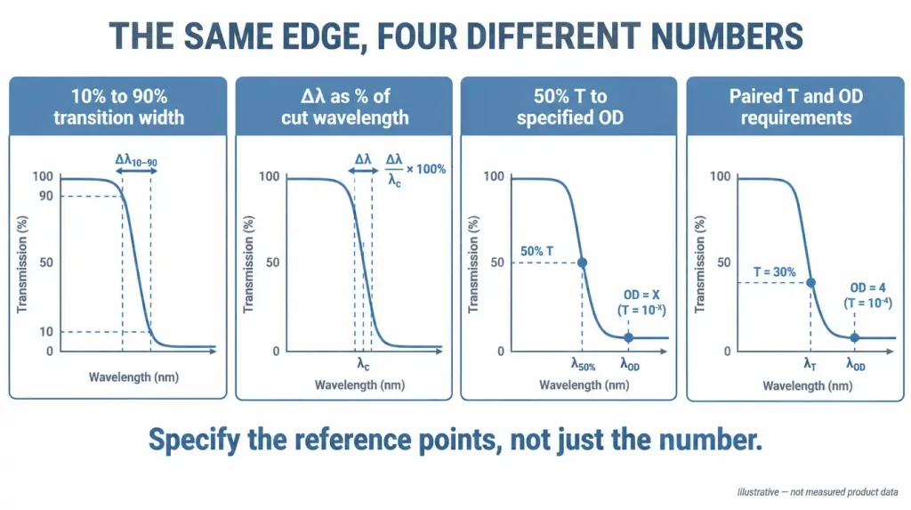
Edge steepness describes how quickly an optical filter transitions between its passband and its blocking region. It is measured as the wavelength interval between two defined reference points on the transition — for example between the 50% transmission point and the wavelength where transmission drops to a specified optical density — and it is quoted either as an absolute value in nanometres or as a percentage of the cut-on or cut-off wavelength. A steeper edge means the filter separates two wavelengths that lie close together; a shallower edge means the transition consumes spectral space that the application may need.
The number itself is meaningless without the two reference points, the angle of incidence and the beam geometry it was measured under. Most disputes about edge steepness between a buyer and a supplier are not disagreements about the coating — they are disagreements about the definition.
How is edge steepness defined on a filter specification?
There is no single universal convention. The same physical coating can be described by several different numbers depending on which reference points are chosen, so a specification has to state them explicitly.
| Convention | How it is expressed | What it actually constrains | Main ambiguity |
|---|---|---|---|
| Absolute transition width | Δλ in nm between two transmission levels, e.g. 10% to 90% | The shape of the visible part of the transition only | Says nothing about deep blocking behaviour |
| Relative (normalised) steepness | Δλ divided by the cut wavelength, expressed as a percentage | Allows comparison across different spectral regions | Meaningless unless the two transmission levels are stated |
| Transmission-to-blocking | Δλ from 50% transmission to a defined OD level | The parameter most applications actually care about | Requires the OD to be measurable at that wavelength |
| Point-pair specification | Two absolute requirements, e.g. T ≥ 90% above λ1, OD ≥ 5 below λ2 | Both the pass side and the block side, with a defined gap | None — this is the testable form |
Two further definitions have to be pinned down alongside it. First, the cut-on or cut-off wavelength itself: it is commonly defined at 50% transmission, but that may be 50% of peak transmission or 50% absolute, and for some applications it is defined at 5% or 80% instead. Second, whether the percentages refer to transmission or to transmittance corrected for substrate reflection losses. A filter with 92% peak transmission has a different 50%-of-peak wavelength than a 50%-absolute wavelength, and on a steep edge the two points can differ by a meaningful fraction of the transition width.
Why does a steeper edge require a more complex coating?
In a dielectric interference filter, the transition between transmission and reflection is produced by the interference of many thin layers of alternating refractive index. The abruptness of that transition is governed by the number of layers, the index contrast between the materials and the design of the matching sections that suppress ripple near the edge. A sharper transition requires more layers and a greater total physical thickness of coating.
That has direct manufacturing consequences. Longer deposition runs increase the accumulated thickness error, so tighter in-situ optical monitoring is needed to keep the edge where the design puts it. Thicker stacks carry more film stress, which can deform thin substrates and affect transmitted wavefront. Uniformity across the clear aperture becomes harder to hold, and a small percentage variation in layer thickness across a large part shifts the edge position at different points on the same filter.
Absorption-based filters behave differently. Coloured glass and other absorbing materials produce a transition governed by the absorption spectrum of the material itself, which is generally gradual and cannot be steepened by design. They are stable with angle and cost-effective, but where the application demands a narrow transition region, an interference coating — often on an absorbing substrate for out-of-band blocking — is the usual route.
What does edge steepness trade off against?
Steepness is not a free parameter that can be maximised in isolation. Pushing it changes other properties of the same filter, and in several applications the resulting compromise is worse than a slightly shallower edge would have been.
| What happens when the edge is pushed steeper | Engineering consequence |
|---|---|
| Layer count and total coating thickness increase | Longer deposition, tighter thickness control, higher sensitivity to process variation |
| Passband ripple near the edge becomes harder to suppress | Transmission close to the cut wavelength may be less flat and less repeatable |
| Angular sensitivity becomes more consequential | The same angular spread that was tolerable on a soft edge now moves the edge across the signal |
| Coating stress rises | Possible substrate deformation, relevant where wavefront or flatness is specified |
| Uniformity tolerance across the aperture tightens | Edge position may vary measurably across a large clear aperture |
| Verification becomes harder | Instrument spectral bandwidth and scan step may limit what can actually be demonstrated |
There is also a temperature dimension. The spectral position of an interference coating drifts with temperature as the layer indices and thicknesses change. On a shallow edge, a small drift is absorbed by the transition width. On a very steep edge specified against a signal only a few nanometres away, the same drift can move the edge onto the wrong side of the signal across the operating temperature range. If the filter runs near a laser, a hot illumination source or in an uncontrolled environment, the operating temperature range belongs in the specification alongside the steepness figure.
How do angle of incidence and cone angle change the effective edge?
An interference filter’s spectral features shift toward shorter wavelengths as the angle of incidence increases. For a filter with effective index neff, the shifted wavelength at angle θ in air follows approximately λ(θ) = λ0 √(1 − sin2θ / neff2). This is a general property of interference coatings, not a characteristic of any particular product.
Two consequences matter for edge steepness specifically:
- A converging or diverging beam degrades the edge. In a cone of light, different rays strike the filter at different angles and each sees a slightly different edge position. The detector integrates over all of them, so the measured system transition is broader than the collimated-beam transition. A filter that meets its steepness specification at 0° collimated may deliver a visibly softer edge in an f/2 beam.
- Non-normal incidence splits s and p polarisation. At an appreciable angle — 45° dichroic geometry being the common case — the s- and p-polarised edges separate. For unpolarised light the effective edge is the combination of the two, which is inherently broader than either. A steep-edge requirement at 45° for unpolarised light therefore constrains the design far more than the same requirement at 0°.
The practical rule: state the angle of incidence, its tolerance, the beam’s cone half-angle and the polarisation state alongside the steepness number. A steepness specification without those conditions is not verifiable.
How is edge steepness measured, and why do measured values disagree?
Edge steepness is verified from a spectral scan, and the instrument itself sets a floor on what can be resolved. Several factors routinely produce different numbers for the same part:
- Spectral bandwidth of the instrument. A monochromator with a spectral bandwidth comparable to the transition width will smear the edge and report a shallower slope than the filter has.
- Scan step. A step size too coarse relative to the transition can miss the true 50% point entirely.
- Beam geometry in the instrument. Sample-compartment beams are not perfectly collimated; residual convergence broadens the measured edge, as above.
- Dynamic range. A standard spectrophotometer cannot verify deep blocking. A steepness figure defined from 50% transmission down to a high OD level cannot be demonstrated on an instrument whose noise floor sits above that OD; the deep-blocking part requires a measurement method with sufficient dynamic range, and the method should be agreed before the specification is fixed.
- Reference basis. Whether percentages are relative to peak transmission or absolute, as discussed above.
This is why a purchase specification should define the measurement condition rather than the number alone. Verification methods and acceptance criteria are agreed against the drawing and the project requirements before production, since a spectral scan proves conformity only when it is taken under the conditions the specification names — visual inspection of a filter says nothing about where its edge sits.
Common mistakes when specifying edge steepness
- Quoting a percentage without transmission levels. “0.5% steepness” is not a specification until it says 0.5% of what, between which two transmission or OD points.
- Comparing vendor datasheets directly. One supplier’s 10–90% figure and another’s 50%-to-OD4 figure describe the same coating with very different numbers.
- Specifying steepness when the real requirement is blocking. Many applications do not need a steep edge; they need a defined rejection at one specific wavelength. Those are different constraints with very different costs.
- Assuming steeper is always better. A steeper edge that drifts with temperature or angle can perform worse in the instrument than a moderate edge with margin designed in.
- Ignoring the assembly. Mounting stress, tilt tolerance in the holder and the actual cone angle at the filter position all change the delivered result relative to the coating specification.
- Requesting steepness that cannot be verified. If neither party can measure it under agreed conditions, it cannot be an acceptance criterion.
How to turn an application requirement into a testable edge specification
Work backwards from the two wavelengths that must be separated, not from a steepness percentage. A fluorescence channel, a Raman configuration and a laser-line rejection each define a signal wavelength that must pass and an interfering wavelength that must be rejected, along with how much rejection is needed for the detector’s dynamic range.
Convert that into paired absolute requirements. Instead of “steep longpass edge near 550 nm”, write the requirement in the form the coating designer and the inspector can both act on:
- Average transmission ≥ 90% over 555–700 nm
- OD ≥ 5 over 500–545 nm
- AOI 0° ± 2°, collimated, unpolarised
- Substrate, clear aperture and outer dimensions with tolerances
- Operating temperature range
- Measurement method and acceptance criteria for both the transmission and the blocking requirement
That form states the transition implicitly — a 10 nm gap between the OD requirement and the transmission requirement — while remaining unambiguous and verifiable. It also lets the designer allocate the available margin sensibly instead of chasing a steepness number that may not serve the application. Where the wavelengths are genuinely close, widening the gap by even a few nanometres, relaxing the OD outside the critical band, or tightening the angular tolerance of the mount often produces a more manufacturable and more stable filter than demanding a steeper edge.
FAQ
Is edge steepness the same as bandwidth or FWHM?
No. FWHM describes the width of a passband between its two half-maximum points. Edge steepness describes how fast the transmission changes at one transition. A bandpass filter has an FWHM and two edges, and those edges can be steep or shallow independently of how wide the passband is.
Does edge steepness apply to longpass, shortpass and bandpass filters equally?
Yes, and to dichroic filters and beamsplitters as well. Any filter with a transition between transmitting and blocking regions has an edge that can be characterised, though for dichroics the 45° geometry and polarisation splitting change how the number must be interpreted.
Can a coloured glass filter have a steep edge?
Not in the sense an interference filter can. The transition in an absorbing glass follows the material’s absorption spectrum and is typically gradual. Its advantages are angular stability and cost, not transition sharpness.
Why does my filter look shallower on the bench than on the datasheet?
The usual causes are beam convergence at the filter, a tilted mount, a measurement made with a wider instrument bandwidth than the datasheet scan, or a comparison between transmission-relative and absolute reference levels. Check the geometry and the measurement conditions before concluding the coating is out of specification.
Does a steeper edge reduce peak transmission?
Not necessarily in the passband centre, but the region immediately adjacent to the edge is where ripple and transmission loss are hardest to control, and more aggressive edge designs make that region more difficult. If high, flat transmission is required close to the cut wavelength, that requirement should be specified separately rather than assumed.
How much margin should I leave between the signal and the edge?
Enough to cover the angular spread at the filter, the temperature range, the manufacturing tolerance on edge position and the measurement uncertainty combined. Those four contributions should be estimated for the actual system rather than taken from a general rule of thumb.
Specifying a filter edge for a project
If an edge specification is being defined for a real optical system, the technically useful starting point is the requirement, not a steepness percentage. Send the drawing, optical specification or sample together with the wavelength range, the wavelengths that must pass and must be blocked with the required OD, the substrate, dimensions and clear aperture, the coating requirement, the angle of incidence and beam cone angle, the polarisation state where relevant, the operating temperature range, the inspection criteria and the expected quantity, and GIAI can review the edge requirement against manufacturing feasibility and define the verification method with it.
