
Technical Resources
What Causes Ghost Images in Beamsplitters?
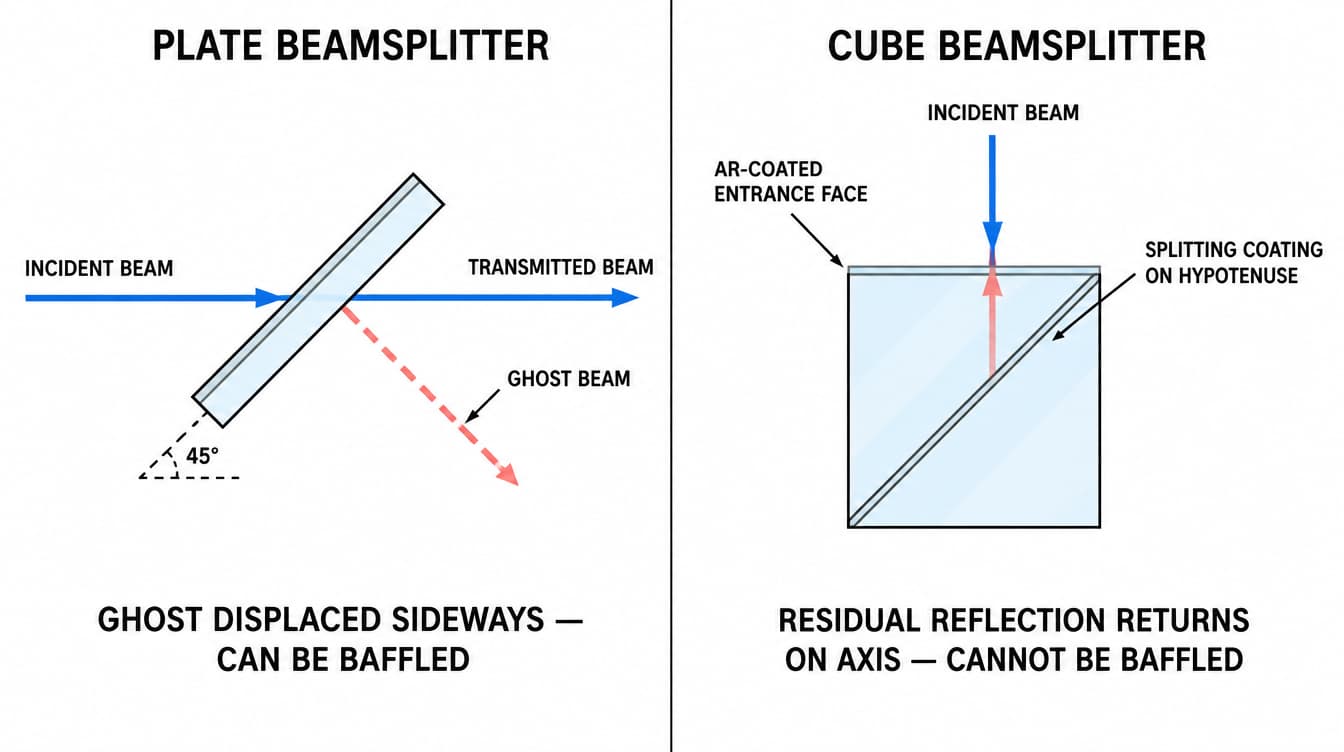
A ghost image in a beamsplitter is a second, weaker image formed by light that reached the detector along an unintended optical path inside the component. In the large majority of cases the path is a reflection from the second surface of a plate beamsplitter, or a residual reflection from an anti-reflection coated entrance or exit face of a cube. Because the splitting coating is designed to reflect a large fraction of the incident light, a residual reflection of only a fraction of a percent somewhere else in the part is enough to produce a visible ghost in a low-signal image.
Ghost images are a geometry and coating problem, not a cleanliness problem. Polishing the part again, or improving surface quality, will reduce scatter and veiling glare but will not remove a discrete, sharply defined second image.
Which surface actually produces the second beam?
Plate beamsplitters: the second surface
A plate beamsplitter carries the splitting coating on surface 1 (S1). Light transmitted through S1 travels through the substrate and reaches surface 2 (S2). If S2 is uncoated, it behaves as an ordinary glass-air interface and reflects part of that beam back into the substrate. That reflected beam exits through S1 parallel to the primary reflected beam, and it is the classic plate-beamsplitter ghost.
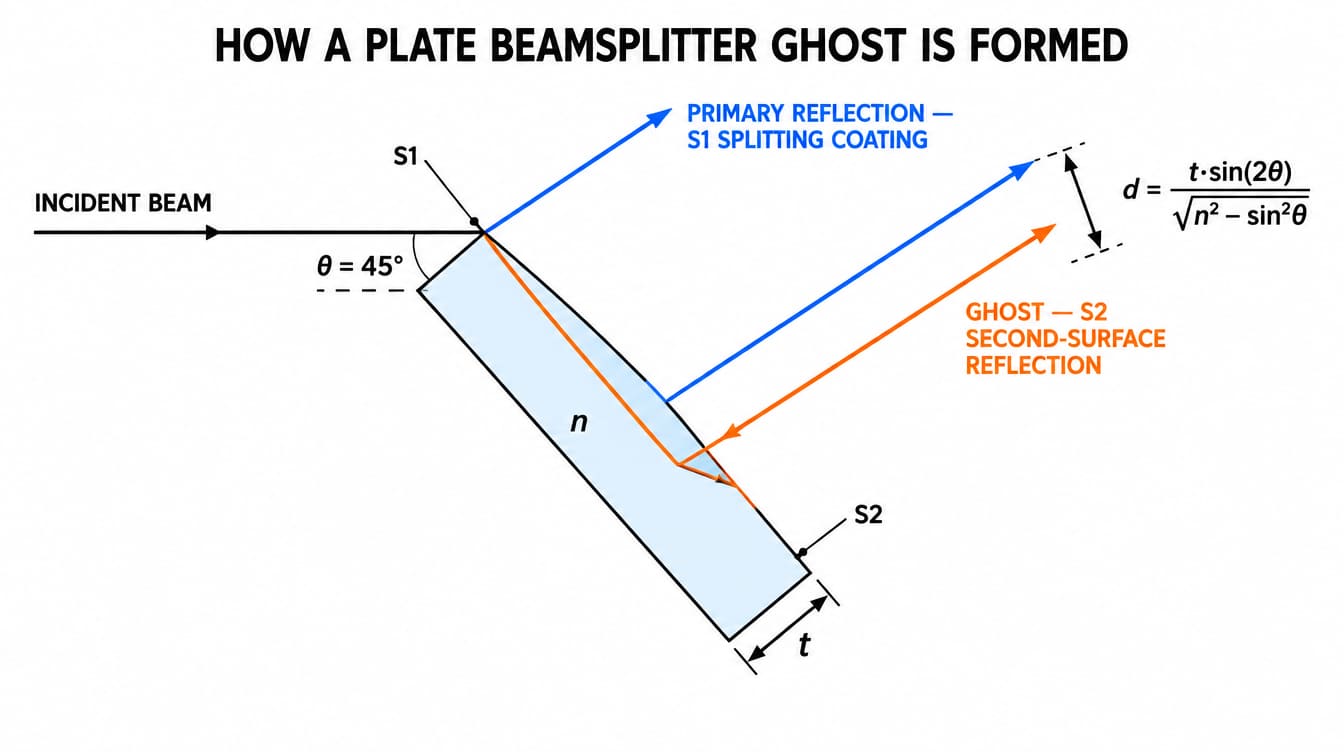
The reflectance of an uncoated S2 is not small in this geometry. For a substrate with n = 1.5168 used at 45° external angle of incidence, the internal ray strikes S2 at about 27.7°, where the Fresnel equations give roughly 9.5% reflectance for s-polarized light and roughly 0.9% for p-polarized light, or about 5% for unpolarized light. The same part can therefore show a strong ghost with s-polarized illumination and a nearly invisible one with p-polarized illumination, with no change to the component.
Cube beamsplitters: the entrance and exit faces
In a cemented cube the splitting coating sits on the internal hypotenuse and the external faces are normally used at near-normal incidence. A residual reflection from an AR-coated entrance or exit face therefore travels back along the optical axis rather than being displaced sideways. This is why cube ghosts are usually described as on-axis flare or as feedback toward the source, while plate ghosts appear as a displaced duplicate image. On-axis ghosts cannot be removed with a baffle and are usually handled by tilting the cube slightly in its mount, or by specifying wedged external faces.
The splitting coating itself
A dielectric splitting coating is not a perfect two-way divider. Part of the beam that has already been transmitted can be reflected back by S2, strike the coating from inside, and be reflected once more into the transmitted channel. Each additional bounce is weaker by roughly the product of the reflectances involved, so second-order ghosts are usually negligible unless both surfaces are highly reflective.
How far is the ghost displaced from the primary beam?
For a plane-parallel plate of thickness t and refractive index n used at external angle of incidence θ, the second-surface reflection leaves parallel to the primary reflection, laterally displaced by:
d = t · sin(2θ) / √(n² − sin²θ)
The displacement scales linearly with thickness, which is the single most useful design lever available before any coating is specified. The values below are calculated directly from this expression for 45° incidence; they are geometric results, not measured product data.
| Substrate thickness | Ghost displacement, n = 1.5168 (BK7-type) | Ghost displacement, n = 1.4585 (fused silica) |
|---|---|---|
| 0.5 mm | 0.37 mm | 0.39 mm |
| 1.0 mm | 0.75 mm | 0.78 mm |
| 2.0 mm | 1.49 mm | 1.57 mm |
| 3.0 mm | 2.24 mm | 2.35 mm |
| 5.0 mm | 3.73 mm | 3.92 mm |
| 6.0 mm | 4.47 mm | 4.70 mm |
Two practical consequences follow. First, a thin plate places the ghost close to or on top of the primary image, where it degrades contrast without ever looking like a separate image. Second, the displacement is fixed and predictable, so measuring the separation of an observed ghost and comparing it with this expression is a fast way to confirm that the substrate second surface is the source.
How bright is the ghost compared with the primary image?
A first-order energy estimate is usually enough to decide whether the ghost matters. Take a nominal 50/50 plate at 45°, unpolarized light, absorption and higher-order bounces ignored. In the reflected channel the primary beam carries 50% of the incident energy. The ghost path is transmission through S1, reflection at S2, transmission back through S1: 0.50 × 0.05 × 0.50 = 1.25% of the incident energy, or about 2.5% of the primary. Against a bright field that is invisible. Against a dark-field or fluorescence image it is not.
Applying an AR coating to S2 that achieves 0.5% residual reflectance at the working angle and waveband reduces the same ghost to roughly 0.25% of the primary, a factor of ten. This is why the second surface of a plate beamsplitter is almost always specified as AR coated, and why an omission of that line from a drawing is one of the most common root causes of a ghost complaint.
Why an AR coating that measured well at 0° still leaves a ghost at 45°
Anti-reflection performance is defined for a stated angle of incidence, polarization state and wavelength band. Move any one of those away from the design point and residual reflectance rises. Three failure patterns recur:
- Angle mismatch. A broadband AR designed and measured at near-normal incidence is being used at 45°. Both the reflectance minimum and the band shift, and s-polarized reflectance rises fastest.
- Band mismatch. The AR band covers the visible imaging channel, while the ghost appears only in the near infrared because an illumination or alignment wavelength outside the specified band was never included in the coating requirement.
- Specification ambiguity. A requirement written as an average reflectance over a band (Ravg) permits local peaks that an absolute maximum requirement (Rabs) would exclude. If the ghost is narrowband, the average value can be met while the reflectance at the operating wavelength is several times higher.
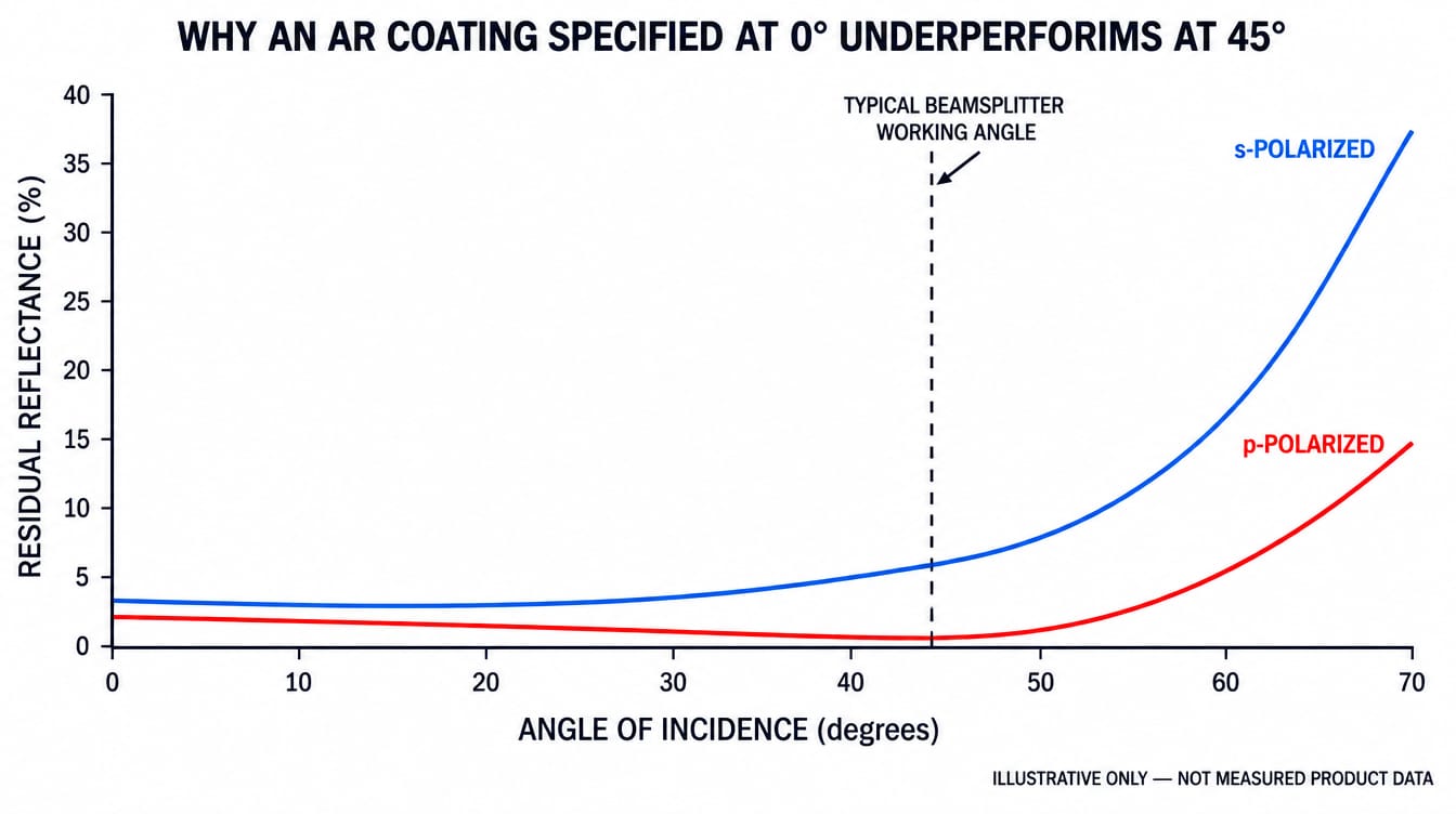
Illustrative only. The curves show the general behaviour of residual reflectance with angle and polarization and do not represent measured product data.
Angle, polarization and band conditions belong in the coating requirement itself. Further background on how coating performance shifts with these conditions is collected in the filters and coatings resources.
When the beamsplitter is not the cause
Before re-specifying the component, confirm that the ghost originates inside it. Common alternative sources produce very similar symptoms:
- The sensor cover glass or microlens array reflects light back toward the beamsplitter, which returns it to the detector.
- A plane-parallel bandpass filter or protective window elsewhere in the path generates its own second-surface ghost, following the same displacement expression with its own thickness.
- Two nominally parallel surfaces in the assembly form a low-finesse cavity, giving a ghost whose position changes as the mount is adjusted.
- The part is installed with S1 and S2 reversed, so the AR-coated face is receiving the splitting duty. This changes both ghost brightness and splitting ratio, and is why the coated face should be identified by a permanent mark on the bevel and called out on the drawing.
Trade-offs in ghost suppression
No approach removes ghosts without cost, and the right choice depends on whether the system can tolerate beam deviation, added thickness or added path length.
| Approach | Effect on the ghost | What it costs |
|---|---|---|
| AR coating on S2 | Reduces ghost energy by roughly an order of magnitude when specified at the correct AOI, polarization and band | Performance is band and angle limited; broad bands and steep angles are harder to satisfy simultaneously |
| Increased substrate thickness | Moves the ghost further from the primary image, so it can be baffled or falls outside the field | More aberration in convergent beams, greater beam displacement in transmission, more mass |
| Wedged substrate | Separates the ghost angularly rather than laterally, so it diverges with propagation distance | Introduces deviation and chromatic dispersion in the transmitted beam that the layout must absorb |
| Cube instead of plate | Eliminates the laterally displaced second-surface ghost and removes transmitted beam displacement | On-axis residual reflections and feedback toward the source; longer glass path; cement layer constraints |
| Pellicle | Substrate is thin enough that the two reflections effectively coincide | Fragile, sensitive to vibration and pressure differentials, and subject to thin-film interference effects |
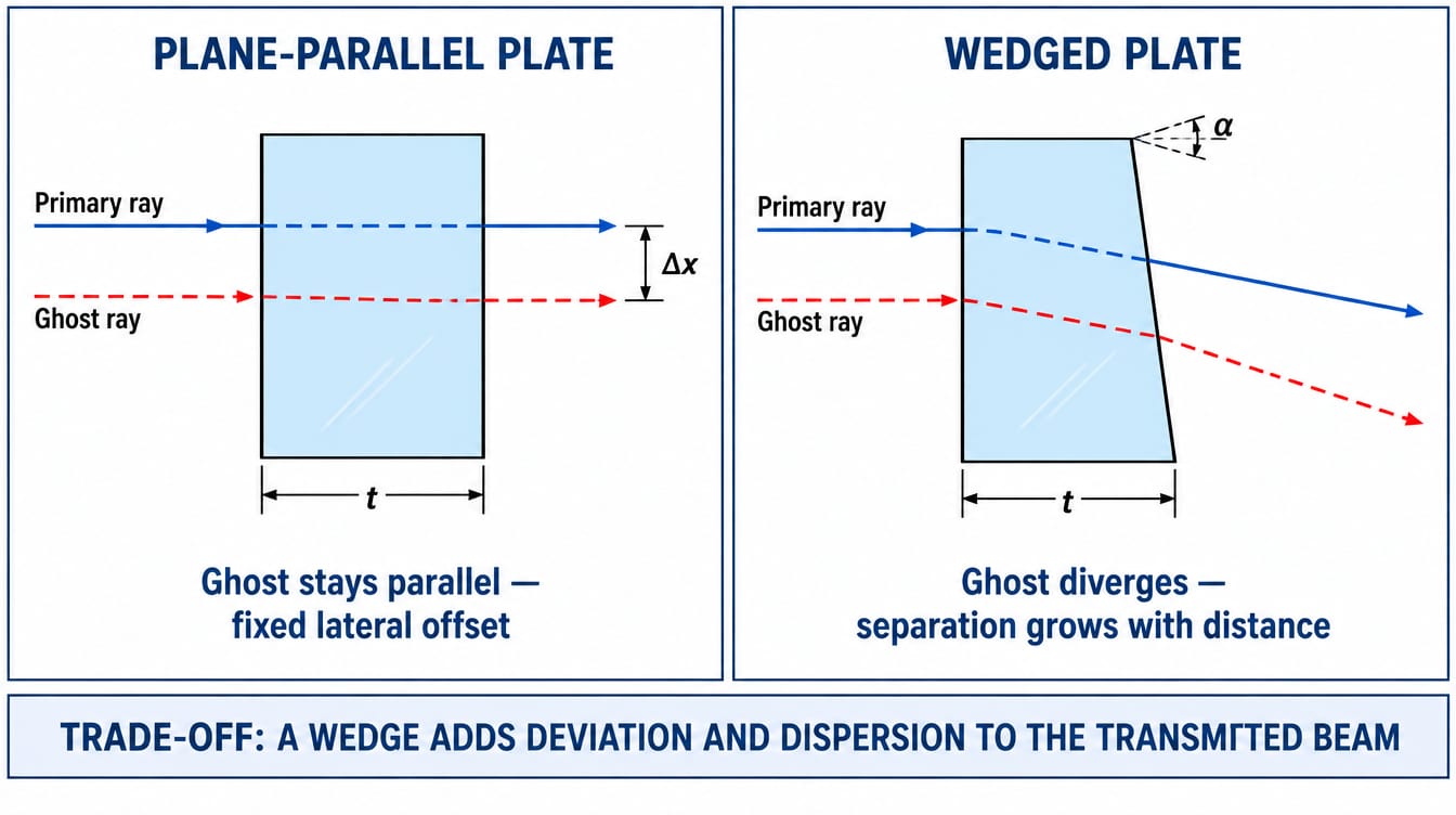
A wedge is the most common answer for laser and interferometric layouts, because angular separation grows with distance and can be made arbitrarily large by moving the detector. It is the wrong answer for imaging systems that cannot tolerate a deviated, dispersed transmitted beam. The required wedge angle should be established by raytracing the actual layout, not by copying a value from another design.
How to identify the responsible surface on the bench
These checks localize a ghost quickly and require no special equipment beyond what is normally present in an optical setup:
- Measure the separation. Compare it with the displacement expression above using the known thickness, index and AOI. A match confirms the beamsplitter second surface.
- Rotate a polarizer in the input beam. A ghost that brightens strongly in s-polarization and nearly disappears in p-polarization points to an uncoated or under-corrected dielectric interface.
- Tilt the component slightly. A ghost from within the beamsplitter moves predictably with the part; a cavity ghost formed with a neighbouring component moves differently or changes intensity.
- Change the wavelength or narrow the band. A ghost that appears only outside the coating band identifies a band specification gap rather than a coating defect.
- Block each downstream element in turn. This separates beamsplitter ghosts from cover-glass and filter ghosts.
What to put on the drawing so the ghost never reaches the bench
Most ghost problems are traceable to an incomplete specification rather than to a manufacturing defect. A beamsplitter drawing that controls ghosting defines at least the following:
- Splitting ratio with the angle of incidence, wavelength band and polarization state at which it applies
- Coating assignment by surface, with the coated face identified by a permanent mark and shown on the drawing
- Second-surface AR requirement stated with AOI, band and whether the limit is an average or an absolute maximum
- Substrate material, thickness and thickness tolerance, since thickness sets ghost displacement
- Wedge angle or surface parallelism, in arcminutes, where the design relies on angular ghost separation
- Clear aperture and coated aperture, with the coated area larger than the clear aperture so edge effects stay outside the working beam
- Surface quality and bevel requirements, which govern scatter and veiling glare rather than discrete ghosts
- Inspection and acceptance criteria, including the conditions under which spectral performance will be verified
The last point is the one most often left open. A spectral requirement without an angle of incidence and polarization condition is not verifiable, because the same coating measured at a different angle returns a different curve. GIAI reviews custom beamsplitter requirements against the drawing, substrate, geometry, coating conditions and inspection criteria before defining the manufacturing and coating route.
Frequently asked questions
Does an AR coating on the second surface eliminate ghost images completely?
No. It reduces the reflected energy at that surface, typically by around an order of magnitude when the coating is specified at the working angle and band, but a residual reflection always remains. Systems with very high dynamic range usually combine an AR coating with a wedge or with sufficient substrate thickness to displace the remainder.
Why does the ghost appear only in one polarization channel?
Fresnel reflectance at a dielectric interface is strongly polarization dependent away from normal incidence. At 45° on a typical glass substrate, s-polarized reflectance is roughly ten times the p-polarized value, so an s-polarized measurement can reveal a ghost that a p-polarized measurement misses entirely.
Is a thicker or a thinner beamsplitter better for ghost control?
Neither is universally better. A thicker plate displaces the ghost further from the primary image, which helps when the ghost can be baffled or pushed out of the field, but it also increases aberration in a convergent beam and shifts the transmitted beam further sideways. The choice depends on whether the layout has room to separate the beams.
Can a ghost image be caused by the splitting coating rather than the substrate?
Yes, but usually as a weaker higher-order effect. Light that has already passed the coating can be returned by the second surface and reflected once more by the coating from inside. This contribution is proportional to the product of the two reflectances and is normally well below the first-order second-surface ghost.
Does surface quality affect ghost images?
Not directly. Scratches, digs and subsurface damage produce scatter and veiling glare, which lower contrast diffusely. A ghost is a sharply defined second image formed by specular reflection, so it responds to coating and geometry changes, not to a tighter cosmetic specification.
How do I convert a ghost complaint into something a supplier can act on?
Provide the measured separation and relative intensity of the ghost, the angle of incidence, the wavelength or band, the polarization state, and the layout position of every component in the path. Those five items usually identify the responsible surface before any part is returned.
Specifying a beamsplitter for your optical path
For a technical review of a plate or cube beamsplitter, send the drawing, optical specification or sample together with the wavelength range, substrate, dimensions, splitting ratio, coating requirements for each surface, angle of incidence and polarization state, wedge or parallelism requirement, inspection criteria and expected quantity. Project background on how custom optical components are evaluated and released is described in the custom optics process, and specifications can be submitted through the contact page.
