
Technical Resources
Protected Aluminum vs Enhanced Aluminum Mirror Coatings
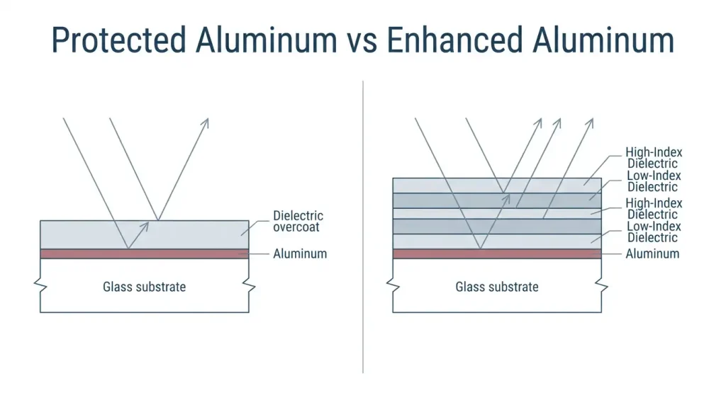
Protected aluminum and enhanced aluminum start from the same vacuum-deposited aluminum film. The difference is what goes on top: protected aluminum adds a single dielectric overcoat that stops oxidation and makes the surface cleanable, with almost no change to the reflectance curve, while enhanced aluminum adds a short dielectric stack tuned to raise reflectance inside one spectral band. Choosing between protected aluminum vs enhanced aluminum mirror coatings is a bandwidth-versus-throughput decision, not a quality decision.
The short version: if the beam is broadband, or the angle of incidence (AOI) varies, or the mirror gets handled often, specify protected aluminum. If the band is fixed, the path contains several folds, and every percent of throughput matters, enhanced aluminum earns its cost.
Why aluminum needs an overcoat at all
Aluminum reflects because its conduction electrons respond almost freely to the incident field, which is described well by the Drude model at long wavelengths. It also oxidizes immediately. A freshly deposited aluminum surface grows a native aluminum oxide (Al₂O₃) layer roughly 2.5 to 3 nm thick on air exposure, and that layer keeps growing slowly with humidity and time.
The oxide itself is transparent, so a small amount is tolerable. The real problem is mechanical: bare aluminum is soft enough that a single wipe with lens tissue leaves visible sleeks, so a bare first-surface mirror can only be cleaned with dry filtered air. In any serviceable instrument, that is not an acceptable maintenance instruction. An overcoat solves both problems, sealing the metal against further oxidation and giving you a surface that survives isopropyl alcohol or acetone and a drag wipe.
Aluminum’s reflectance is not flat, and no coating fixes that
Aluminum sits near 90 percent through most of the visible, dips through roughly 700 to 900 nm, then recovers and climbs above 95 percent in the mid-infrared. That dip is not a coating defect. It comes from a parallel-band interband absorption in aluminum near 1.5 eV, which corresponds to about 800 nm. It is a property of the metal.
This matters for coating selection because the loss budget is fixed by physics. For an opaque mirror, transmission is essentially zero, so:
R + A + S = 1
where R is reflectance, A is absorption in the metal and coating layers, and S is scatter. Whatever you do not reflect turns into heat or stray light. A dielectric stack over aluminum can redistribute where the reflectance peaks, but it cannot remove the metal’s absorption underneath.
What each coating actually is
Protected aluminum
A single dielectric overcoat on the aluminum, commonly silicon monoxide (SiO) or silicon dioxide (SiO₂), typically near half-wave optical thickness at a reference wavelength. A half-wave layer is chosen deliberately because at that thickness it is close to optically absent, so the coating protects the metal without reshaping the reflectance curve much.
Published catalog specifications for standard protected aluminum are around R<sub>avg</sub> greater than 85 percent over 400 to 700 nm and greater than 90 percent over 400 to 2000 nm, with the near-infrared (NIR) figure benefiting from aluminum’s recovery past the 800 nm dip.
Enhanced aluminum
A short multilayer stack over the aluminum, usually alternating high and low index oxides such as SiO₂ paired with titanium dioxide (TiO₂) or tantalum pentoxide (Ta₂O₅). Four to six layers is typical. Each interface contributes a partial reflection, and the layer thicknesses are set so those partial reflections add in phase with the reflection from the metal at the design wavelength.
A standard visible enhanced aluminum runs around R<sub>avg</sub> greater than 95 percent over 450 to 650 nm. UV-enhanced and deep-UV variants use different materials and are specified in the 250 to 450 nm and 190 to 600 nm regions respectively.
The gain is real but bounded. You are stacking interference on top of a metal that still absorbs, so a handful of layers takes you from roughly 88 to roughly 95 percent, and further gains flatten out quickly. Getting to 99 percent means abandoning the metal for an all-dielectric high reflector, which brings a much narrower usable band, tighter AOI tolerance, and higher cost.
Comparison: protected vs enhanced aluminum
| Parameter | Protected aluminum | Enhanced aluminum |
|---|---|---|
| Coating structure | Aluminum plus one dielectric overcoat | Aluminum plus 4 to 6 dielectric layers |
| Typical R<sub>avg</sub>, visible | >85% (400–700 nm) | >95% (450–650 nm) |
| Typical R<sub>avg</sub>, extended | >90% (400–2000 nm) | Not specified outside design band |
| Usable bandwidth | Very broad, UV through IR | Limited to the design band |
| AOI tolerance | High; curve changes slowly with angle | Lower; band shifts blue with angle |
| S/P polarization split at 45° | Present, moderate | Present, and amplified by the stack |
| Typical published LIDT | 0.3 J/cm² at 532 and 1064 nm, 10 ns | 0.2 J/cm² at 532 nm, 10 ns |
| Coating stress on figure | Low | Higher; matters on thin substrates |
| Cleanability | Good; IPA or acetone drag wipe | Good; comparable |
| Relative cost | Baseline | Higher |
The laser-induced damage threshold (LIDT) row surprises people. Edmund Optics publishes 0.3 J/cm² for protected aluminum and 0.2 J/cm² for enhanced aluminum under nanosecond pulsed conditions. Adding layers does not automatically raise damage threshold, because each added interface is another place for absorbing defects and field enhancement. LIDT values are strongly supplier-specific and test-condition-specific, so treat any single number as indicative and ask for the test conditions.
Datasheet parameters that decide the choice
Reflectance specification form. R<sub>avg</sub> and R<sub>min</sub> are not the same promise. An R<sub>avg</sub> greater than 95 percent over 450 to 650 nm is satisfied by a curve that touches 91 percent at one band edge. If you have a single laser line, ask for R<sub>min</sub> at that wavelength, at your AOI, in your polarization state.
Angle of incidence. Interference coatings shift toward shorter wavelengths as the angle increases. The standard approximation is:
λ(θ) = λ₀ · √(1 − sin²θ / n_eff²)
With an effective index near 1.8, a coating centered at 550 nm at normal incidence lands near 505 nm at 45 degrees, about an 8 percent shift. For a metal-based enhanced design n_eff is only an approximation, so use it to anticipate the direction and rough size of the shift, then ask the coater for the curve at your actual AOI.
Polarization. At oblique incidence, s-polarized reflectance is higher than p-polarized for both coatings. The dielectric stack in an enhanced design adds its own splitting because the s and p band edges move by different amounts. In a polarization-sensitive system such as ellipsometry or a polarization-maintaining fold, this is a specification you have to write down, not one to leave to the coater.
Surface figure and clear aperture. Coating stress can bend a substrate. A common shop practice is to keep the diameter-to-thickness ratio at 6:1 or lower for figure-critical mirrors, and enhanced coatings, with more layers and more accumulated stress, are the more demanding case. If you specify λ/10 peak-to-valley (P-V) at 632.8 nm, state whether that applies before or after coating, and over what clear aperture.
Surface quality and drawing convention. Scratch-dig is called out under MIL-PRF-13830B; 60-40 is common for general optics and 20-10 or 10-5 for laser and low-scatter work. ISO 10110 gives the equivalent surface imperfection notation for drawings written to ISO convention. Choose one system per drawing rather than mixing them.
Durability. Environmental durability for front-surface aluminized mirrors is commonly referenced to MIL-M-13508C, and interference coating durability to MIL-C-48497A, which covers adhesion, moderate abrasion, humidity, and solubility. ISO 9211-4 defines the equivalent test methods. Both coating types can be built to pass these; ask which specific tests a given part number has actually been run against, because “meets MIL spec” without a test list means very little.
GIAI Photonics supplies optical mirrors and custom optical coatings, and specifying the AOI, polarization state, and post-coating figure requirement up front is what keeps a coating run from being requoted.
The engineering trade-offs
Every percent of reflectance you buy with an enhanced design costs you bandwidth and angular tolerance. That is the whole trade in one sentence.
The throughput argument is what usually justifies the cost. Reflectance compounds across folds as R^N. Over six reflections, 85 percent gives 0.85⁶ = 0.38, while 95 percent gives 0.95⁶ = 0.74. Nearly a factor of two in system throughput, from a coating change on parts you were buying anyway.
The bandwidth argument runs the other way. Enhanced aluminum’s advantage exists only inside the design band. Outside it, reflectance is not guaranteed and in some designs falls below what protected aluminum would have given you at the same wavelength. If your source is a white-light LED, a supercontinuum, or a broadband thermal emitter, an enhanced visible mirror can leave you with less light than the cheaper coating.
Dispersion is a third consideration. A multilayer introduces more wavelength-dependent phase than a single half-wave overcoat. This is irrelevant for continuous-wave work, but for femtosecond pulses an unspecified enhanced stack will broaden the pulse, and that calls for a mirror carrying a phase specification, not just a reflectance one.
Common specification mistakes
Reading R<sub>avg</sub> as if it were R<sub>min</sub>. The classic failure: a 640 nm laser line placed at the upper edge of a 450 to 650 nm enhanced band, where the curve is already rolling off. The mirror meets its spec and the system still comes up short on power.
Ordering a normal-incidence design for a 45 degree fold. An enhanced coating designed at 0 degrees and installed in a periscope or a galvo fold loses several percent at the short end of the band and picks up an s-p split it was never specified to control. Always state the AOI on the purchase order.
Using enhanced visible aluminum in the NIR. A 450 to 650 nm enhanced mirror used at 850 or 940 nm is operating in undefined territory, right where the metal’s own 800 nm absorption sits. For machine vision systems that switch between visible inspection and NIR illumination, protected aluminum’s broader guaranteed range is usually the safer specification, and protected silver is worth evaluating if the band sits between 450 and 800 nm.
Cleaning a metal mirror like a dielectric one. Both coatings tolerate a solvent drag wipe. Neither tolerates scrubbing, and neither tolerates strong alkaline cleaners, which attack aluminum through pinholes in the overcoat. Pinhole corrosion shows up as scattered dark spots months after installation, usually in humid environments, and it is the most common field failure mode on aluminum mirrors.
Coating a thin substrate without checking figure. A 100 mm diameter, 6 mm thick fused silica flat specified at λ/10 P-V can come back at λ/4 after an enhanced coating run. Specify figure after coating, or thicken the substrate.
How to choose
Choose protected aluminum when the spectral range spans more than roughly one octave, when the AOI varies or is unknown at design time, when the mirror is a service item that gets cleaned, when the same part number has to cover visible and NIR operation, or when the budget matters more than the last few percent of throughput.
Choose enhanced aluminum when the band is defined and narrow enough to be covered by a 200 nm wide design, when three or more folds make the R^N compounding significant, when the AOI is fixed and stated, and when the improvement has been checked against R<sub>min</sub> at the working wavelength rather than R<sub>avg</sub> across the band.
Consider stepping outside the aluminum family when the requirement is above about 97 percent, in which case protected silver covers 450 to 800 nm at higher reflectance, protected gold suits the NIR and IR, and an all-dielectric high reflector is the answer for a single laser line where you can accept the narrow band and the cost.
FAQs
How much reflectance do I actually gain by moving from protected to enhanced aluminum? Roughly 8 to 10 percentage points inside the design band, typically from the mid-80s to about 95 percent in the visible. Whether that is worth the cost depends on how many reflections are in the path. One fold gains little. Six folds nearly doubles throughput, since reflectance compounds as R^N.
Is enhanced aluminum more durable than protected aluminum? Not inherently. Both put dielectric material over the metal and both can be built to the same abrasion, adhesion, and humidity requirements. The multilayer is not automatically harder, and it carries more coating stress. Judge durability by the test list a supplier has actually run, not by the number of layers.
Can I use an enhanced aluminum mirror at 45 degrees if it was specified at normal incidence? Mechanically yes, optically at your own risk. The band shifts toward shorter wavelengths by roughly 8 percent at 45 degrees, and s and p reflectance separate. If your wavelength sits near the short edge of the band, the shift may help; near the long edge, it will hurt. Specify the AOI and ask for the curve at that angle.
Why does aluminum have a reflectance dip near 800 nm, and can a coating remove it? It comes from a parallel-band interband absorption in aluminum near 1.5 eV. It is intrinsic to the metal. A dielectric design can raise reflectance in a narrow region around it, but the absorption remains underneath. If you need high reflectance through 700 to 900 nm, silver or gold is the better base metal.
Which coating survives cleaning better in a production environment? They are comparable. Both accept a solvent drag wipe with isopropyl alcohol or acetone and clean lens tissue. Neither should be scrubbed or exposed to alkaline cleaners. In high-humidity installations, corrosion through overcoat pinholes is a larger long-term risk than abrasion for either coating.
Do these coatings drift with temperature? Reflectance itself is fairly stable over normal instrument temperature ranges for both. The parameter that actually moves is surface figure, through coating stress and the mismatch in thermal expansion between coating and substrate. On thin or large mirrors, budget for figure change rather than reflectance change.
If you are specifying first-surface mirrors for a visible or NIR system, GIAI Photonics’ optical mirrors and custom optical coatings can be quoted against either coating type once the AOI, band, and post-coating figure requirement are defined.
