
Technical Resources
Ultra Narrow Bandpass Filter Applications: Engineering Guide
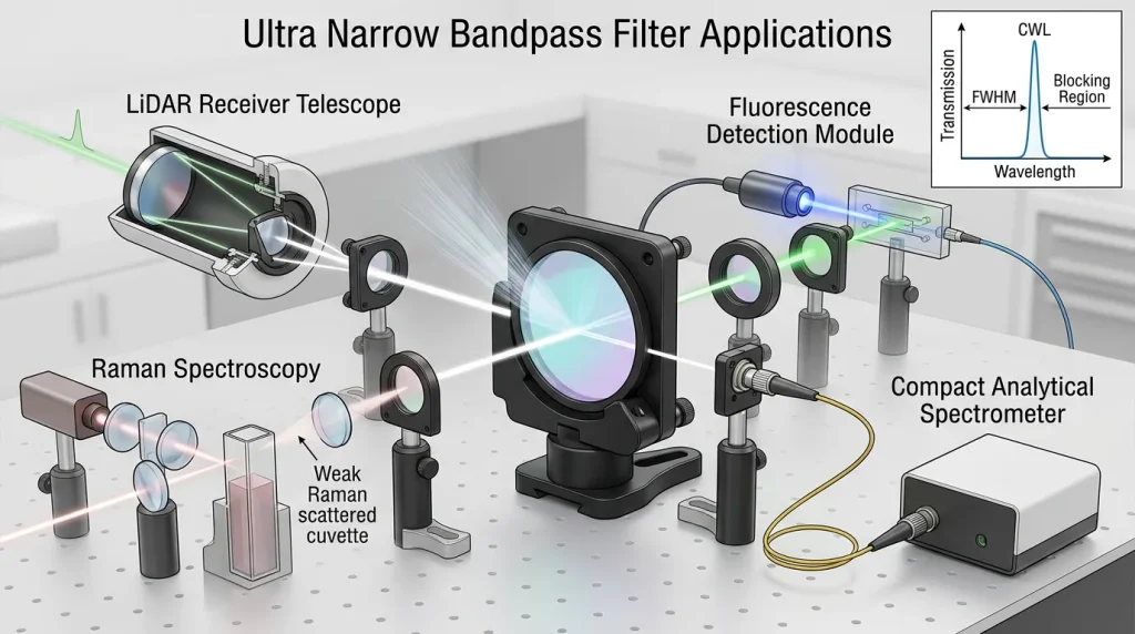
An ultra narrow bandpass filter is used when an optical system needs to transmit a tightly defined wavelength region while strongly attenuating light outside that region. Typical ultra narrow bandpass filter applications include laser-line cleanup, LiDAR and active optical sensing, selected fluorescence channels, analytical spectroscopy, astronomical emission-line imaging, and other systems in which a useful optical signal must be separated from a much broader spectral background.
The important engineering point is that narrower is not automatically better. Once the passband becomes very narrow, center-wavelength tolerance, source wavelength drift, angle of incidence, beam convergence, polarization and temperature can become as important as nominal FWHM. An ultra-narrow filter should therefore be selected as part of the optical system rather than from bandwidth alone.
What Makes a Bandpass Filter “Ultra Narrow”?
There is no universal industry boundary separating a narrow bandpass filter from an ultra-narrow bandpass filter. The term generally describes a bandpass whose spectral width is very small relative to its center wavelength. Depending on wavelength and application, this may mean several nanometers, approximately one nanometer, or a sub-nanometer passband.
For engineering purposes, the name matters less than the actual spectral specifications. The most important quantities are:
- Center wavelength (CWL): the specified central location of the transmission band.
- Full width at half maximum (FWHM): the wavelength interval between the two points where transmission reaches half of the passband maximum.
- Peak transmission: the highest transmission reached within the passband.
- Average or minimum passband transmission: often more useful than peak transmission when the complete signal band must be transmitted.
- Blocking range: the wavelength interval over which out-of-band rejection is specified.
- Optical density (OD): a logarithmic description of transmitted leakage in the blocking region.
- Angle of incidence (AOI): the angle between the incident ray and the surface normal.
Here, T is transmission expressed as a fraction. For example, OD 4 corresponds to a transmitted fraction of 10-4, or 0.01%. OD should not be interpreted as reflectance. A low transmission level may result from reflection, absorption, scattering, or a combination of these mechanisms. In a dielectric interference filter, much of the rejected optical power is normally reflected, but the exact energy balance depends on the coating and substrate.
How an Ultra Narrow Bandpass Filter Works
Most precision ultra-narrow bandpass filters are based on multilayer dielectric interference structures. Alternating layers with different refractive indices create wavelength-dependent constructive and destructive interference. The coating is designed so that a narrow spectral region experiences high transmission while wavelengths outside the passband are strongly rejected.
Multi-cavity designs can be used when a flatter transmission band and steeper spectral edges are required. Increasing spectral selectivity, however, generally increases coating-design and manufacturing sensitivity. Small errors in optical layer thickness become increasingly significant when the required passband is extremely narrow.
The substrate remains important as well. The transmission range of the bare substrate does not define the spectral performance of the finished filter. A substrate may be transparent over a wide wavelength range while the completed coating intentionally transmits only a fraction of that range.
1. LiDAR and Active Optical Sensing
LiDAR receivers and other active optical sensors often operate in environments containing large amounts of broadband background radiation. The transmitted laser occupies a relatively narrow spectral region, while sunlight, artificial lighting and other sources can contribute photons across much of the detector’s responsivity range.
A narrow receive-side bandpass filter placed before the detector can reduce this background while transmitting the returned laser wavelength. When the background spectral density is approximately continuous across the passband, reducing the optical bandwidth also reduces the amount of background radiation reaching the detector.
The filter bandwidth cannot simply be reduced indefinitely, however. The passband must still accommodate:
- laser wavelength tolerance;
- laser wavelength drift with temperature and operating conditions;
- filter CWL manufacturing tolerance;
- filter temperature shift;
- AOI variation across the receiver field;
- the angular cone produced by the collection optics.
A filter specified at normal incidence in a collimated laboratory beam may therefore behave differently in a fast receiver lens. For an ultra-narrow filter, even a relatively small spectral shift can represent a substantial fraction of the total FWHM.
2. Laser-Line Selection and Laser Cleanup
Ultra-narrow bandpass filters are frequently used close to laser sources to transmit the desired laser line while suppressing unwanted spectral components such as amplified spontaneous emission, residual pump wavelengths, neighboring laser modes or broadband source background.
This is commonly called laser cleanup. In this position, passband transmission directly affects usable laser power, while blocking requirements are determined by the unwanted spectrum produced by the actual source.
Power handling must be evaluated separately from spectral rejection. A coating with very high out-of-band reflectivity or OD is not automatically suitable for a high-power laser. Laser-induced damage threshold depends on coating materials, deposition quality, pulse duration, wavelength, beam diameter, defect population and the test method used to characterize the optic.
Back-reflection also deserves attention. Because interference filters may reflect substantial out-of-band power, the mechanical orientation and optical layout should prevent unwanted reflected light from coupling back into a sensitive laser source.
3. Raman Spectroscopy
Raman systems are an important application for highly selective optical filters, but the role of each filter must be distinguished carefully.
An ultra-narrow laser-line bandpass filter can be used in the excitation path to clean the laser spectrum before it reaches the sample. This reduces broadband source emission that could otherwise create unwanted background in the measured spectrum.
The detection path usually has a different requirement. Raman instruments often need to measure a range of wavelengths shifted away from the excitation laser, so the primary rejection element is commonly a steep longpass, shortpass or notch filter that rejects the much stronger Rayleigh-scattered laser line while transmitting the Raman-shifted spectrum.
This distinction is especially important when specifying a complete optical filter set. The excitation filter, dichroic element and detection-side rejection filter perform different spectral functions.
4. Fluorescence Excitation and Detection
Fluorescence systems also use bandpass filters on both sides of the optical path. An excitation filter restricts illumination to the wavelength region used to excite the fluorophore, while an emission filter limits the wavelengths reaching the detector.
An ultra-narrow passband can be useful when spectral channels are closely spaced, when narrow-line excitation must be isolated, or when a particular emission feature must be separated from neighboring optical background.
But fluorescence spectra are often relatively broad. Making the emission filter unnecessarily narrow can discard useful fluorescence photons and reduce signal. The correct bandwidth is therefore determined by the fluorophore spectrum, excitation leakage, detector response, neighboring channels and the required signal-to-background ratio.
In fluorescence systems, deep blocking may be just as important as passband width because excitation light can be much stronger than the detected emission. Peak transmission alone is consequently not enough to describe filter suitability.
5. Spectroscopy and Spectral-Line Detection
Analytical instruments sometimes need to isolate a specific absorption or emission region rather than measure an entire continuous spectrum. A narrow bandpass filter can form one spectral channel in photometers, chemical sensors, flame or plasma measurements, and other wavelength-selective instruments.
The required FWHM should follow the spectral feature being measured. If the filter is substantially wider than the feature, additional background reaches the detector. If it is narrower than the useful feature, part of the signal is rejected.
For absorption measurements, a reference channel may also be required so that changes in source intensity, optical contamination or detector response are not mistaken for absorption by the target material. The filter does not determine analytical accuracy by itself; source stability, path length, detector noise, calibration and sampling conditions remain part of the measurement chain.
6. Machine Vision and Structured-Light Systems
Active machine-vision systems often illuminate a scene at a known wavelength and place a bandpass filter in front of the camera. The objective is to increase spectral separation between the controlled illumination and ambient light.
Ultra-narrow filters may be appropriate for narrow-spectrum laser illumination. They are less suitable when the source itself has a broad spectrum. For example, an LED can occupy a much wider wavelength interval than a stabilized laser, and its spectrum may shift with temperature. A passband that is narrower than the source can reduce the usable illumination reaching the camera.
The same issue appears with wide-field camera lenses: rays can reach the filter over a range of incidence angles. A very narrow filter that performs well in a spectrophotometer may shift or broaden when installed in front of a lens with a wide field of view.
7. Astronomy and Emission-Line Imaging
Narrow spectral filtering can isolate emission features from nebulae and other astronomical objects while suppressing a large fraction of broadband sky background. This is a natural application for highly selective bandpass filters because the desired spectral information can occupy a much narrower region than the surrounding optical background.
Optical geometry again matters. A filter used in a converging telescope beam receives rays over multiple incidence angles rather than at one single AOI. The resulting wavelength distribution can shift and broaden the effective passband. The effect becomes increasingly important as FWHM decreases.
Why Angle of Incidence Becomes Critical
The spectral position of a dielectric interference filter changes with incidence angle. A simplified approximation for the angular dependence of the passband is:
where λ(0) is the reference wavelength near normal incidence and neff represents an effective refractive index of the multilayer structure. The expression is an approximation; the real response must be calculated from the actual coating design.
As AOI increases, the passband generally moves toward shorter wavelengths. At non-zero AOI, s- and p-polarized light can also develop different spectral responses. This is why a performance curve measured at 0° should not be assumed to represent operation at 30°, 45°, or across a fast converging beam.
For wide-field or high-NA systems, specify not only the chief-ray AOI but also the angular distribution reaching the filter.
Application Comparison
| Application | Main Function of Filter | Key Parameters | Common Integration Risk |
|---|---|---|---|
| LiDAR / active sensing | Pass return wavelength and suppress ambient background | CWL, FWHM, blocking range, OD, AOI | Passband shift across receiver cone |
| Laser cleanup | Suppress unwanted laser-source spectrum | Peak transmission, nearby blocking, CWL tolerance, LIDT | Source drift or back-reflection |
| Raman excitation | Clean excitation laser spectrum | CWL, narrow FWHM, nearby OD, transmission | Confusing cleanup filter with Raman rejection filter |
| Fluorescence | Select excitation or emission channel | Band placement, blocking, transmission, channel separation | Bandwidth too narrow for useful fluorescence spectrum |
| Analytical spectroscopy | Isolate an absorption or emission region | FWHM, CWL accuracy, blocking, temperature stability | Mismatch between filter band and spectral feature |
| Machine vision | Separate controlled illumination from ambient light | Source bandwidth, FWHM, AOI, detector response | LED spectrum or field angle wider than filter acceptance |
| Astronomy | Isolate a narrow emission feature | CWL, FWHM, transmission, cone-angle performance | Fast optical beam shifts effective passband |
How to Specify an Ultra Narrow Bandpass Filter
A useful specification begins with the optical system rather than with a nominal filter name. At minimum, determine the following.
1. Define the signal wavelength range
Specify the actual signal spectrum, including source tolerance and temperature drift. Do not assume that a nominal 850 nm, 905 nm, 940 nm or 1550 nm source remains at exactly that wavelength under all operating conditions.
2. Set FWHM from the total wavelength budget
The filter must transmit the full useful signal after source drift, filter tolerance and angular shift are included. A narrower FWHM is valuable only if it does not remove part of the required signal.
3. Specify blocking depth and blocking range separately
“OD 5” is incomplete without a wavelength interval. A filter can provide deep rejection near the passband while allowing leakage elsewhere. The required blocking range should consider the spectrum of the source, the environment and the detector’s spectral responsivity.
4. State the real AOI and beam geometry
Specify normal incidence, a defined oblique AOI, or the complete cone angle as appropriate. If the optic will operate near 45°, polarization behavior should be considered explicitly.
5. Distinguish peak from usable passband transmission
A high peak transmission value at one wavelength does not guarantee high throughput over the entire required signal range. For flat-top or multi-wavelength applications, minimum or average transmission across the required passband can be the more meaningful specification.
6. Consider substrate and mechanical requirements
Dimensions, thickness, clear aperture, surface quality, transmitted wavefront, wedge or parallelism may matter if the filter is located in an imaging or collimated optical path. These mechanical and optical specifications are independent of FWHM and OD.
Common Mistakes When Selecting Ultra-Narrow Filters
- Choosing the narrowest available FWHM without calculating source and AOI drift.
- Using a 0° spectrum to predict performance at a large AOI.
- Comparing OD values without comparing the specified blocking ranges.
- Treating peak transmission as transmission across the whole passband.
- Assuming low transmission means the rejected energy is absorbed rather than reflected.
- Assuming a transparent substrate guarantees transmission after coating.
- Assuming high reflectivity or high OD implies a high laser-damage threshold.
- Ignoring polarization when the interference filter operates at an oblique angle.
Conclusion
Ultra narrow bandpass filters are most valuable when the desired optical signal occupies a much smaller spectral region than the unwanted background. This makes them useful in LiDAR, laser-line cleanup, selected Raman and fluorescence functions, analytical spectroscopy, active machine vision and astronomical emission-line imaging.
The practical design question is not simply how narrow the filter can be made. It is how narrow the passband can remain while still transmitting the required signal under real source wavelength variation, temperature, manufacturing tolerance, AOI, polarization and optical-system geometry.
For engineering selection, CWL, FWHM, passband transmission, OD, blocking range and AOI should therefore be treated as a connected specification set. Evaluating those parameters together is more reliable than choosing an ultra-narrow filter from nominal wavelength or bandwidth alone.
