
Technical Resources
Thermal Lensing in Germanium Optics
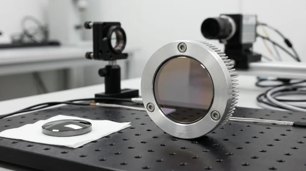
Thermal lensing in germanium optics is the change in optical power that occurs when absorbed radiation heats a germanium element non-uniformly, creating a radial temperature gradient that is converted into a refractive index gradient through the material’s thermo-optic coefficient. The heated element behaves as if a weak additional lens had been inserted into the beam path — focus moves, spot size grows, and wavefront error increases, all without any physical change to the surfaces. Germanium is more prone to this than almost any other infrared material, not because it conducts heat poorly, but because its index changes with temperature roughly six times faster than zinc selenide and forty times faster than fused silica.
This article separates three effects that are frequently discussed as if they were one: thermal lensing, thermal defocus, and thermal runaway. They have different causes, different symptoms and different fixes.
What thermal lensing actually is
An optical element absorbs some fraction of the radiation passing through it. In a transmissive component, absorbed power is deposited preferentially where the irradiance is highest — usually the centre of the aperture. Heat then flows radially outward toward the mount, so the element reaches a steady state with the centre hotter than the rim.
Three coupled mechanisms turn that temperature profile into an optical error:
- Refractive index gradient (dominant in germanium). The thermo-optic coefficient dn/dT describes how much the refractive index changes per kelvin. A hot centre and cool rim means a higher index on axis, which adds optical path length on axis. For a material with positive dn/dT, this acts as a positive (converging) lens.
- Surface deformation. Thermal expansion causes the heated region to bulge, changing the local radius of curvature. This is usually secondary in germanium but not negligible in thick windows.
- Stress-induced birefringence. The temperature gradient produces mechanical stress, which makes the index polarization-dependent. In a well-mounted element this is a small effect; in an over-constrained mount it can dominate and appear as astigmatism or depolarization.
For a collimated beam of radius w passing through a thickness L of material with absorption coefficient α and thermal conductivity κ, the steady-state thermal lens focal length scales approximately as:
Order-of-magnitude scaling only. It assumes steady state, uniform absorption along the path, radial heat flow to a fixed-temperature rim, and it ignores surface bulging, coating absorption and stress. Use it to understand which parameters matter, not to predict a number.
The useful conclusion from that expression is what it contains: thermal lens strength rises with dn/dT and with absorbed power, and falls with thermal conductivity and with the square of the beam radius. Doubling the beam diameter through the element reduces the thermal lens by roughly a factor of four. That is often the cheapest available fix.
Why germanium is unusually susceptible
Germanium is chosen for MWIR and LWIR work because it transmits from roughly 2 µm to 14 µm, has a very high refractive index near 4.0, and shows low dispersion across the LWIR band, which allows compact lens forms with few elements. The same material also carries an unusually large thermo-optic coefficient.
| Material | n (near band of use) | dn/dT (×10⁻⁶ K⁻¹) | κ (W·m⁻¹·K⁻¹) | (dn/dT)/κ |
|---|---|---|---|---|
| Germanium | ≈ 4.00 (10 µm) | ≈ +400 | ≈ 59 | ≈ 6.8 |
| Silicon | ≈ 3.42 (4 µm) | ≈ +160 | ≈ 150 | ≈ 1.1 |
| GaAs | ≈ 3.28 (10 µm) | ≈ +150 | ≈ 55 | ≈ 2.7 |
| ZnSe | ≈ 2.40 (10.6 µm) | ≈ +61 | ≈ 18 | ≈ 3.4 |
| ZnS (multispectral) | ≈ 2.20 (10 µm) | ≈ +40 | ≈ 27 | ≈ 1.5 |
| Chalcogenide IR glass | ≈ 2.6 (10 µm) | ≈ +30 to +90 | ≈ 0.2–0.5 | high |
Representative room-temperature values for orientation only. Actual figures depend on grade, wavelength, temperature and supplier; always take dn/dT and κ from the datasheet for the specific material lot being used.
Two things stand out. First, germanium has the largest dn/dT in the table by a wide margin. Second, its thermal conductivity is genuinely good — better than ZnSe or ZnS — which partly offsets the index sensitivity. The ratio in the last column shows that on gradient sensitivity alone, germanium is only about twice as bad as ZnSe. The much larger difference lies elsewhere: in how much power each material absorbs in the first place.
Where the heat comes from: absorption in germanium
Germanium is a semiconductor with a bandgap near 0.67 eV, giving an intrinsic absorption edge around 1.8 µm. Well beyond that edge, in the 8–14 µm band and specifically at the CO₂ laser wavelength of 10.6 µm, lattice absorption is small and the residual absorption is dominated by free-carrier absorption. Free electrons and holes in the conduction and valence bands absorb long-wavelength photons, and the strength of that process scales with carrier concentration.
This is why bulk resistivity appears on germanium datasheets. Lower resistivity means higher doping, higher carrier concentration and therefore higher absorption. Optical-grade germanium is specified at moderate to high resistivity for exactly this reason. It is also why free-carrier absorption is markedly weaker in the MWIR band than in the LWIR band — the process becomes much stronger at longer wavelengths, so a germanium element that behaves well at 4 µm may be far more troublesome at 10.6 µm under the same irradiance.
The temperature feedback loop
Carrier concentration in germanium is not fixed. As temperature rises, thermally generated intrinsic carriers multiply, so absorption rises, so more power is deposited, so the temperature rises further. This positive feedback is the origin of thermal runaway, the behaviour that makes germanium different in kind from ZnSe rather than merely different in degree.
In practical terms, germanium transmission begins to degrade measurably somewhere around 60 °C, falls sharply approaching 100 °C, and germanium is effectively opaque in the LWIR by roughly 200 °C. Most system designs therefore treat 100 °C as an absolute ceiling and design for a much lower operating temperature to retain margin. Once runaway begins, the element can heat quickly enough to fracture.
Absorption that is not in the substrate
In a low-absorption substrate, the coating and the surface condition often dominate the heat load. Anti-reflection coatings are essential on germanium — with n ≈ 4.0 the Fresnel reflection is about 36 % per surface, so an uncoated germanium window transmits under 50 % before any absorption is considered. But a coating reduces reflection loss; it does not reduce bulk absorption, and a poorly deposited coating stack, or a hard protective layer such as DLC on an external surface, contributes its own absorption at the surface where cooling is best but where damage initiates most readily. Fingerprints, oil films and particulate contamination behave the same way and are a very common cause of localized heating on components that previously performed correctly.
Thermal lensing vs thermal defocus vs thermal runaway
These three terms describe different physics and are routinely used interchangeably, which makes troubleshooting reports difficult to interpret.
| Thermal lensing | Thermal defocus (soak) | Thermal runaway | |
|---|---|---|---|
| Driver | Temperature gradient across the aperture | Uniform temperature change of optic and housing | Absorption increasing with temperature |
| Typical setting | Laser transmission, high-irradiance beams | Passive thermal imaging over ambient range | High average power through Ge, or poor heatsinking |
| Symptom | Focus and spot size drift after power is applied; settles at steady state | Focus shifts with ambient temperature; MTF drops at temperature extremes | Transmission falls progressively and accelerates; element may fracture |
| Reversible? | Yes, on cooling | Yes | Only if caught early; often ends in permanent damage |
| Main countermeasure | Lower absorbed power, larger beam, better rim cooling | Optomechanical or optical athermalization | Lower absorption grade, power limit, active cooling, material change |
Passive LWIR imaging systems almost never suffer true thermal lensing, because scene radiance deposits negligible power. What they suffer is thermal defocus: as the whole assembly warms, germanium’s large dn/dT shifts the focal length while the aluminium housing simultaneously changes the element spacing. Athermalized designs exploit this deliberately, pairing germanium with a material of very different dn/dT, or with a diffractive surface, so the two contributions cancel over the operating range.
Symptoms and diagnosis
When a germanium element is suspected of thermal problems, the first task is to determine whether the effect is thermal at all, and if so, whether the heat source is the substrate, the coating, contamination, the mount or the measurement setup.
Characteristic symptoms
- Time dependence. Thermal effects have a time constant. If beam quality or focus position is correct at switch-on and degrades over seconds to minutes before stabilizing, the cause is almost certainly thermal. A defect that is present immediately and does not evolve is not.
- Power dependence. Reduce average power and observe. Thermal lensing scales with absorbed power; a fabrication error does not.
- Reversibility. Allow the element to cool fully and re-measure. Full recovery points to lensing or reversible transmission loss; incomplete recovery points to coating damage or bulk change.
- Symmetry. A rotationally symmetric focus shift suggests bulk gradient lensing. Astigmatism appearing under load suggests mount-induced stress. A localized hot spot suggests contamination or a coating defect.
Measurement methods
- Spectral transmission before and after (FTIR, at room temperature). Establishes whether the component itself has changed. Note that this measures the finished coated element, not the substrate — the two are different quantities, and a substrate transmission curve should never be used to predict a coated component’s performance.
- Absorption measurement by laser calorimetry. The direct way to separate absorption from scatter and reflection loss. ISO 11551 describes the method for optical laser components. Transmission measurement alone cannot do this: a low transmission value may come from reflection, scatter or absorption, and only absorption produces heat.
- Thermal imaging of the mounted element. Reveals whether the gradient is centred on the beam (bulk or coating absorption) or offset toward one edge (poor thermal contact with the mount).
- Interferometric transmitted wavefront under load. Germanium is opaque in the visible, so a visible interferometer cannot be used in transmission. Measurement requires an IR interferometer — commonly at 10.6 µm, or at 3.39 µm or 1.55 µm where the element still transmits.
- Focus position tracking with a beam profiler. Record focal plane position against time and against power to obtain the thermal lens directly.
Separating the possible causes
| Observation | Most likely source | Confirming test |
|---|---|---|
| Effect scales smoothly with power, symmetric, fully reversible | Bulk substrate absorption | Calorimetric absorption on a witness sample; check resistivity grade |
| Heating concentrated at one surface; damage initiates there | Coating absorption or coating defect | Compare front/back surface temperature; inspect coating under IR microscope |
| Localized spot, appeared after handling or servicing | Contamination | Clean by an approved procedure and re-measure; inspect under grazing illumination |
| Astigmatism or birefringence appearing under load | Mount stress, over-constraint, mismatched CTE | Re-measure de-mounted; check retaining ring torque and adhesive pattern |
| Rim much hotter than expected, poor cooling | Thermal interface resistance at the mount | Thermal imaging of the housing; verify contact area and interface material |
| Effect disappears when the reference arm or detector is changed | Measurement setup, not the component | Repeat with an independent instrument and a known-good reference optic |
Design and specification guidance
Controlling thermal lensing in germanium optics is mostly a matter of controlling absorbed power and heat extraction. Practical measures, roughly in order of effectiveness:
- Specify absorption, not just transmission. Require a maximum absorption coefficient at the operating wavelength, measured on the finished coated element, together with the substrate resistivity range. Transmission specifications alone do not constrain the heat load.
- Reconsider the material for high-power transmission. For CO₂ laser transmissive optics, ZnSe typically shows absorption at 10.6 µm one to two orders of magnitude below optical-grade germanium and has no runaway mechanism. Germanium remains an excellent choice for imaging optics and for low-power or reflective roles, but it is a poor choice for high average power transmission. Selecting between them is a system decision, not a ranking of materials — germanium’s high index and low LWIR dispersion give it optical advantages ZnSe cannot match.
- Enlarge the beam. Because the thermal lens scales with 1/w², placing the germanium element where the beam is large is often more effective than any material change.
- Reduce thickness. Absorbed power is proportional to path length. Thin the element to the minimum consistent with mechanical stiffness and surface figure.
- Heatsink the rim properly. Germanium’s thermal conductivity is only useful if the heat has somewhere to go. Ensure a real conductive path from the element edge to the housing without over-constraining it mechanically.
- Athermalize imaging designs. For passive systems, address defocus at design stage through material pairing, diffractive surfaces or optomechanical compensation rather than through refocusing in the field.
- Control cleanliness in service. A contaminated surface can initiate localized runaway on a component that met all specifications at delivery.
Common misunderstandings
- “Germanium conducts heat well, so thermal lensing is not a concern.” Conductivity helps, but the very large dn/dT and the temperature-dependent absorption dominate the outcome.
- “An AR coating reduces heating.” It reduces reflection loss and raises transmission. Bulk absorption is unchanged, and the coating adds a small absorption of its own.
- “The datasheet transmission curve tells me how much power the optic can take.” It does not. Transmission loss can be reflection, scatter or absorption, and only the absorbed fraction becomes heat. Absorption must be measured separately.
- “High reflectivity means the mirror can handle high power.” Reflectivity and damage resistance are independent properties. A 99.5 % reflector with an absorbing defect will fail before a 98 % reflector that is clean and well cooled.
- “Room-temperature specifications apply in the field.” For germanium in particular, they do not. Both dn/dT and absorption change significantly across an operating range, and performance at 25 °C says little about performance at 80 °C.
- “Normal-incidence data applies at any angle.” Coating performance and Fresnel losses are angle- and polarization-dependent. A window specified at 0° will behave differently at 45° AOI, and the resulting absorbed power will differ too.
Summary
Thermal lensing in germanium optics is a direct consequence of two material properties working together: a thermo-optic coefficient near 400 × 10⁻⁶ K⁻¹, far higher than competing infrared materials, and a free-carrier absorption that increases with temperature and creates a runaway feedback path at 10.6 µm. Germanium remains the natural material for LWIR imaging because of its index and dispersion. It becomes a liability when significant average power passes through it.
The engineering response is to treat absorption as a specified, measured quantity rather than an inferred one; to distinguish clearly between gradient lensing, uniform-temperature defocus and runaway when describing a problem; and to check time dependence, power dependence and reversibility before concluding that an element is defective. Many reported “germanium quality problems” turn out to be thermal management problems, contamination, or a measurement made under conditions the component was never specified for.
Frequently asked questions
At what temperature does germanium stop transmitting infrared light?
Germanium transmission in the LWIR band degrades measurably from roughly 60 °C, drops sharply as the element approaches 100 °C, and is effectively lost by about 200 °C. The mechanism is free-carrier absorption: thermally generated carriers increase with temperature, absorption rises, and the element heats further. Because this feedback accelerates, most designs treat 100 °C as an absolute limit and target a substantially lower steady-state temperature to retain margin. The exact behaviour depends on resistivity grade, thickness and wavelength, so figures should be verified for the specific material rather than assumed.
What is the difference between thermal lensing and thermal defocus?
Thermal lensing is caused by a temperature gradient across the aperture, which produces a refractive index gradient and adds optical power. It appears when a beam deposits heat non-uniformly, typically in laser systems. Thermal defocus is caused by a uniform temperature change of the optic and its housing, shifting focal length and element spacing together. It appears in passive thermal imaging across an ambient range, with no beam power involved. The two require different remedies: better cooling and lower absorption for lensing, athermalized design for defocus.
How much power can a germanium window handle at 10.6 µm?
There is no single figure, because the limit depends on absorption coefficient, thickness, beam diameter, mount cooling and ambient temperature. Germanium is generally regarded as suitable only for low average power at 10.6 µm, and thermal lensing or runaway typically becomes the limiting factor well before any coating damage threshold is reached. For meaningful numbers the absorbed power must be measured calorimetrically for the specific coated element and combined with a thermal model of the actual mount, rather than taken from a general datasheet.
Does germanium exhibit thermal lensing in the 3–5 µm MWIR band?
Less severely than at 10.6 µm, but the mechanism is the same. Free-carrier absorption becomes considerably stronger at longer wavelengths, so germanium absorbs less in the MWIR than in the LWIR for a comparable irradiance and heats more slowly. The thermo-optic coefficient remains large across both bands, so once heating does occur the index gradient is just as sensitive. MWIR operation reduces the heat input but does not remove the underlying susceptibility.
Can an anti-reflection coating prevent thermal lensing?
No. An AR coating addresses reflection loss, which is substantial on germanium because the refractive index near 4.0 gives about 36 % Fresnel reflection per uncoated surface. Raising transmission this way improves throughput but does not change the bulk absorption that generates heat, and the coating stack contributes a small absorption of its own. Coating quality does matter for a different reason: a poorly deposited or contaminated coating can become a localized absorber and initiate damage at the surface.
How do I confirm that a focus shift is thermal rather than a fabrication error?
Check three things. First, time dependence: a thermal effect develops over seconds to minutes after power is applied and then stabilizes, whereas a fabrication error is present immediately. Second, power dependence: reduce average power and see whether the effect scales. Third, reversibility: allow full cooling and re-measure, since a thermal lens disappears completely. If all three behaviours are present, the cause is thermal, and the next step is to determine whether the heat originates in the substrate, the coating, contamination or the mount.
