
- A thin film coating manufacturer controls design, substrate cleaning, deposition and metrology; weakness in any stage shows up as spectral or durability failures.
- Deposition process sets film density, which drives moisture shift, stress, scatter and absorption.
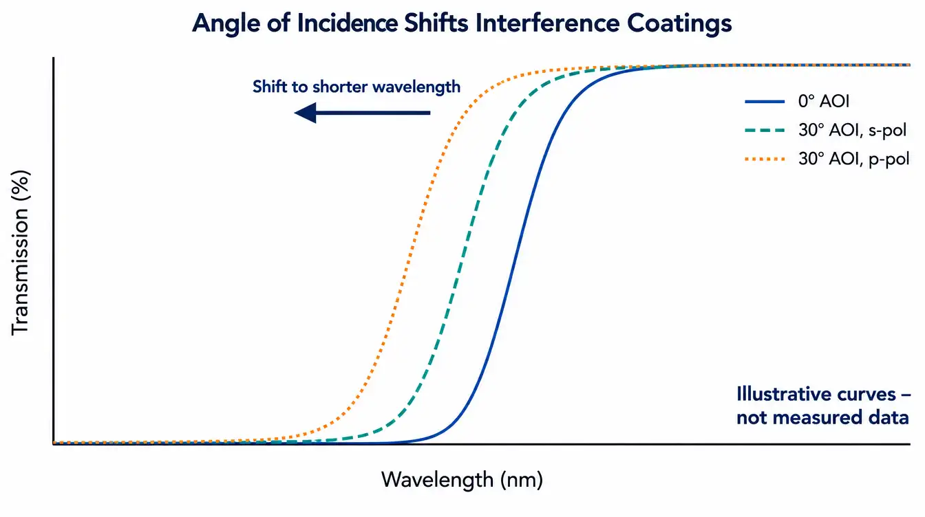
- Interference coatings shift toward shorter wavelengths as angle of incidence increases, so every spectral target needs an AOI and polarization.
- Agree before ordering whether acceptance is measured on the part or on a witness sample, and by which method.
- ISO 9001 certifies a quality management system, not the spectral performance of a coated part.
A thin film optical coating manufacturer designs and deposits dielectric multilayers or metallic films that set how an optic reflects, transmits or blocks light. Choosing one means checking four things: the coating types it can design, the deposition process it uses, how it verifies spectra at your angle of incidence, and which durability tests it can document.
What does a coating manufacturer actually control?
Four stages decide whether a coated optic meets its specification: thin-film design, substrate preparation and cleaning, deposition with in-situ thickness monitoring, and post-coating metrology. A supplier that controls all four can trace a spectral deviation or an adhesion failure to its cause. A supplier that only runs the chamber has to rely on someone else for the other three.
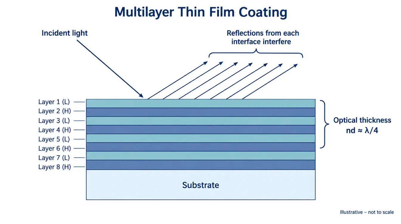
Most optical coatings work by thin-film interference. Alternating layers of high- and low-refractive-index materials, many with an optical thickness near a quarter of the design wavelength (nd = λ/4), make the reflections from each interface add or cancel. Layer count, material pair and thickness accuracy together set the bandwidth, edge steepness and blocking a design can reach. Metallic coatings work differently: aluminum, silver or gold provide broadband reflection, and dielectric overcoats protect the metal or raise its reflectance over a chosen band.
A single layer shows the scale of the effect. At normal incidence and 587.6 nm, an uncoated BK7-type crown glass surface (n = 1.517) reflects 4.2%, so two uncoated surfaces lose 8.3% of the incident light, ignoring multiple reflections. A quarter-wave MgF2 layer (n = 1.38) lowers that surface to 1.3%. These are calculated Fresnel values for non-absorbing, ideally smooth surfaces, not measured product data.
Which coating types should the manufacturer be able to design?
The coating types you need determine which suppliers are realistic candidates. Anti-reflection, mirror, filter and beamsplitter coatings each stress a different part of the process, from thickness control to material absorption. The table lists what each type does and what makes it difficult.
| Coating type | Function | Key specs | Most sensitive to |
|---|---|---|---|
| AR (V-coat or broadband) | Reduce surface reflection | R per surface over band, AOI | Bandwidth vs minimum reflectance, AOI range |
| Metallic mirror (Al, Ag, Au) | Broadband reflection | Average R over band, AOI, overcoat | Environmental exposure, absorption |
| Dielectric high reflector | High reflection over a limited band | R at wavelength, AOI, polarization, LIDT | Bandwidth, AOI shift, layer thickness errors |
| Bandpass and edge filters | Transmit one band, block others | CWL or cut-on/cut-off, FWHM, T, OD, blocking range | AOI, cone angle, temperature, moisture shift |
| Beamsplitter and dichroic | Split by ratio, wavelength or polarization | R/T at AOI, polarization state | s/p separation at oblique incidence |
| Metal-dielectric ND | Attenuate across a band | OD and its flatness over band | Absorption heating, back reflection |
Spectral region also changes the material set. Titanium dioxide, a common high-index material for visible and near-infrared designs, absorbs in the ultraviolet, so UV coatings move to materials such as hafnium oxide and aluminum oxide. Mid- and long-wave infrared coatings on germanium or ZnSe substrates use infrared-transparent coating materials such as germanium and zinc sulfide.
How does the deposition process change coating performance?
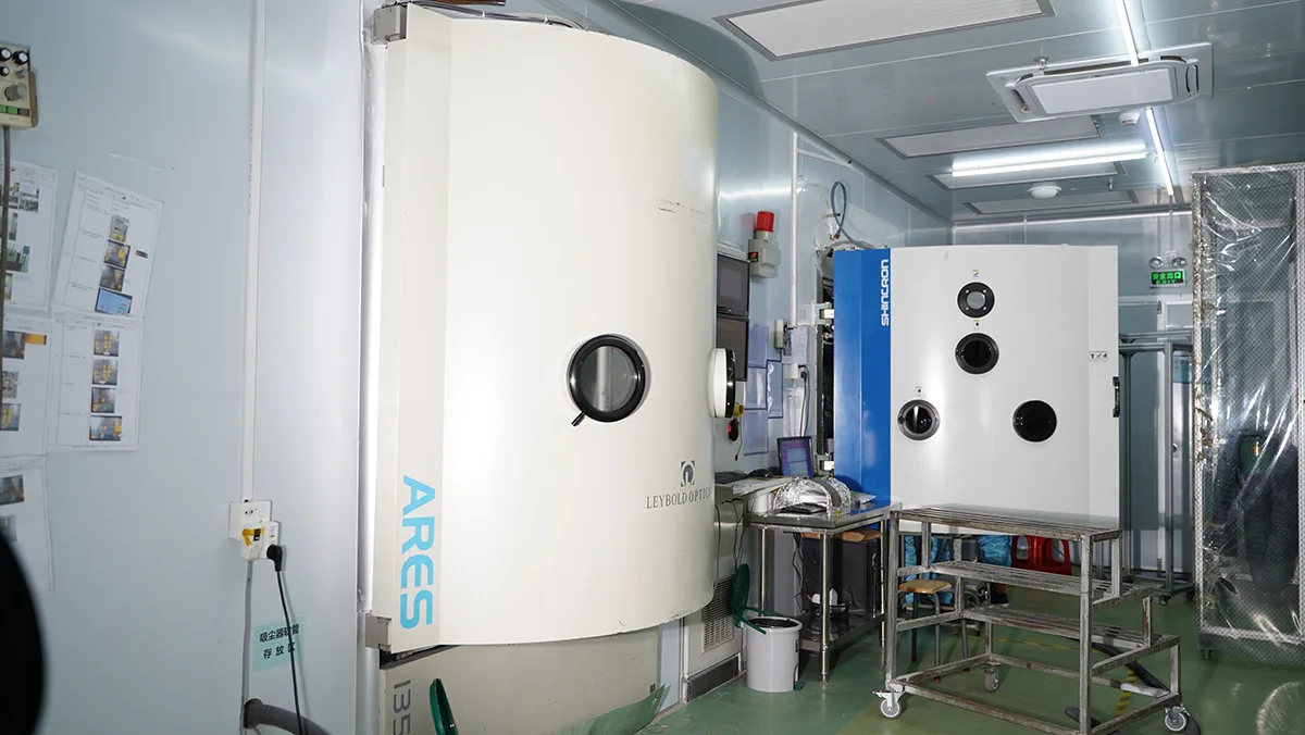
The deposition process sets film density, and density drives spectral stability, absorption, scatter and stress. Conventional electron-beam or thermal evaporation grows columnar films with voids. When the part leaves vacuum, water fills those voids, raises the effective refractive index and shifts spectral features toward longer wavelengths. Energetic processes pack films more densely and reduce that shift.
| Process | Film density | Moisture shift | Relative throughput | Engineering note |
|---|---|---|---|---|
| E-beam / thermal evaporation | Lower, porous | Present | High, large batches | Wide material choice; spectrum moves between vacuum and air |
| Ion-assisted deposition (IAD) | Higher | Reduced | High | Ion bombardment densifies films at lower substrate temperature |
| Magnetron sputtering | High | Low | High for suited geometries | Stable rates suit hard-coated filters and large areas |
| Ion beam sputtering (IBS) | Highest | Low | Lower | Low scatter and absorption; slower growth, smaller coating zone |
Relative ratings compare processes in general terms; actual results depend on the specific chamber, materials and process parameters.
Density brings its own cost. Dense energetic films usually carry compressive stress, and a thick filter stack on a thin substrate can bow the part enough to change flatness and transmitted wavefront. Thicker substrates, backside balancing coatings or stress-tuned processes reduce the effect. Substrate temperature matters too: dense oxide films from plain evaporation often rely on substrate heating, which polymers, cemented parts and some pre-assembled components cannot tolerate. Ask which process the supplier uses for your coating family, not only which machines it owns.
What trade-offs shape a coating specification?
Every coating specification balances spectral performance against layer count, angular tolerance, durability and verifiability. Tightening one requirement costs margin on another, so identify the parameter your system cannot compromise first.
Layer count against stress and sensitivity
More layers give steeper edges, deeper blocking and flatter passbands. They also add run time, accumulated stress, cumulative absorption and scatter, and sensitivity to thickness errors in each layer. For a given material set, a V-coat reaches very low reflectance at one wavelength, while a broadband AR spreads low reflectance over a wide band and accepts higher residual reflectance at any single wavelength.
Angle of incidence and polarization
Interference coatings shift toward shorter wavelengths as the angle of incidence increases, and s- and p-polarized light separate at oblique incidence. The shift follows λ(θ) = λ0·√(1 − sin²θ / neff²). For an 850 nm feature with an assumed effective index of 2.0, the calculated position moves to 846.8 nm at 10° and 837.5 nm at 20° in air. These are calculated values for collimated light; a converging beam averages over its cone and broadens the edge.
Blocking depth against verifiability
A specified optical density is only useful if it can be measured. Deep blocking can exceed the dynamic range of a standard spectrophotometer, so the specification should state the measurement method and the level at which the instrument limit is reported. An OD value without a blocking range and measurement condition cannot be accepted or rejected.
Durability against spectral performance
Unprotected silver reflects strongly from the visible into the infrared but tarnishes in air. A protective dielectric overcoat improves environmental resistance and also changes reflectance and its angular behavior.
How is coating performance verified before acceptance?
Coating acceptance rests on spectral measurement under stated conditions, plus durability and cosmetic tests tied to the drawing. The key decisions are where the spectrum is measured, at what AOI and polarization, and which durability standard applies.
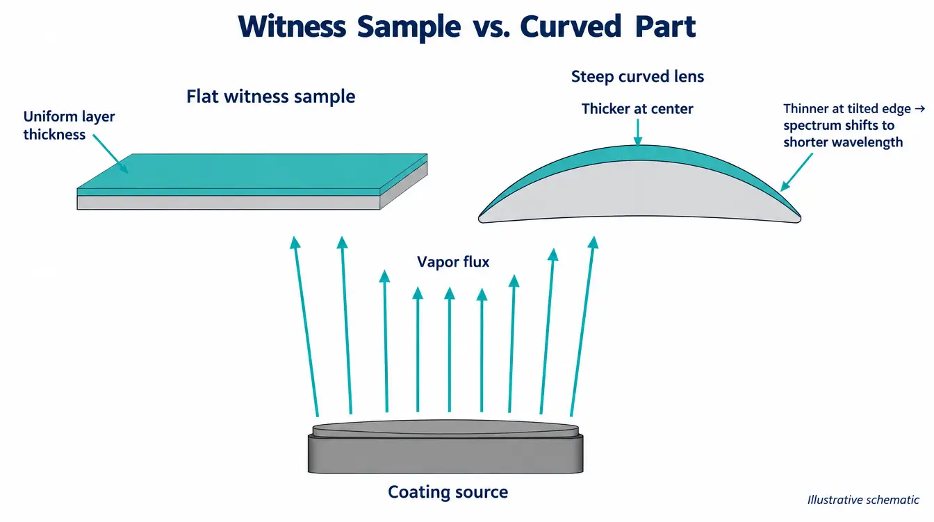
Spectrophotometers measure transmission and reflection, but a normal-incidence curve does not prove performance at 45°. For beamsplitters, dichroics and anything used off-axis, request data at the working AOI and polarization. Small parts, curved lenses and prisms are often verified on flat witness samples coated in the same run. Witness data is a proxy. On a steeply curved lens, areas where the surface tilts away from the vapor flux receive thinner layers, which shifts their spectrum toward shorter wavelengths unless fixturing or masking compensates.
Durability requirements should name a standard. MIL-C-48497A covers single and multilayer interference coatings, MIL-C-675C covers anti-reflection coatings on glass, and ISO 9211-3 and ISO 9211-4 cover environmental durability and specific test methods for optical coatings. MIL-C-48497A, for example, includes adhesion, humidity and abrasion tests; whichever standard applies, the specification must name the tests and levels required. For laser optics, laser-induced damage threshold depends on wavelength, pulse duration, repetition rate and beam size, so an LIDT figure is only comparable when those conditions are stated, as in the ISO 21254 test method series.
On drawings, ISO 10110-9 provides the notation for surface treatment and coating, including which surface is coated.
How should you evaluate a thin film optical coating manufacturer?
Evaluate a coating supplier on evidence tied to your specification: measured curves with conditions, a stated deposition process, a defined acceptance method and documented durability testing. Equipment lists say little about whether your coating will pass.
- Can you share measured curves for a comparable design, with AOI, polarization and measurement instrument stated?
- Which deposition process will you use for this coating, and how much moisture shift and stress should we expect?
- Do you fabricate the substrate, or coat parts we supply? Who is responsible for cleanliness and surface defects before coating?
- Is acceptance measured on the part or on a witness sample, at which AOI, and with what sampling plan?
- Which durability tests do you run in-house, to which standard and test level?
- Can you provide data from more than one coating run, so run-to-run variation is visible?
- Will you notify us before changing coating materials, process or equipment on a released design?
Quality-system documentation belongs in the same review. Confirm the certificate holder, certified scope, site and validity dates through the supplier’s certifications and compliance documentation, and remember that ISO 9001 certifies a management system rather than the spectral performance of a coated part. GIAI reviews custom coated optics against the drawing, sample, optical requirements, substrate, geometry, coating conditions and inspection criteria before defining the manufacturing route; the steps are outlined on the custom optics process page, with inspection logic on the quality assurance page.
Which specification mistakes delay coating projects?
Most coating delays start with a specification that cannot be built or verified as written, usually because conditions are missing. Each item below forces a round of clarification or a rejected first article.
- Writing “R < 0.5%” without the band, AOI, polarization, or whether the value is per surface, average or maximum.
- Giving a collimated AOI for a coating that sits in a converging beam, without the cone half-angle.
- Specifying OD without a blocking range and a measurement method.
- Treating one sample curve as a production guarantee.
- Leaving the coated surface, clear aperture, masked areas and edge treatment undefined on the drawing.
- Ignoring the environment: humidity, temperature range and the cleaning solvents the part will see.
- Setting a spectral tolerance tighter than the system needs.
For filter-specific parameters such as CWL, FWHM and blocking, the filters and coatings resources go deeper into each specification.
What information does a coating RFQ need?
A coating RFQ needs the optical function, spectral targets with their conditions, substrate details and the acceptance method. With those, a supplier can judge feasibility in one pass.
- Optical function and coating type for each surface (AR, mirror, filter, beamsplitter).
- Wavelength range and spectral targets: R or T values, CWL, FWHM, cut-on or cut-off, OD and blocking range.
- AOI, cone half-angle and polarization at the coated surface.
- Substrate material, dimensions, thickness and whether you supply the parts.
- Clear aperture, coated area and masking on a drawing.
- Operating environment, durability standard and test level.
- Acceptance method: on part or witness, measurement conditions, report format.
- Quantity for prototype and production.
Coated components are grouped by family under optical filters, optical mirrors and beamsplitters, and process scope is described under manufacturing capabilities.
FAQ
What are thin film optical coatings?
Thin film optical coatings are layers of dielectric or metallic material, deposited onto lenses, windows, mirrors and filters, that control reflection and transmission. Dielectric multilayers use interference between reflections at each layer boundary, while metallic coatings reflect directly. They are used to reduce reflection, build mirrors, select wavelength bands and split beams.
How are optical coatings made?
Precision optical interference coatings are commonly made by physical vapor deposition in a vacuum chamber. Common methods are electron-beam or thermal evaporation, ion-assisted deposition, magnetron sputtering and ion beam sputtering. Layer thickness is controlled in real time, often with optical or quartz-crystal monitoring. The method chosen affects film density, moisture-induced spectral shift, stress, absorption and throughput.
How do you test optical coatings?
Optical coatings are tested for spectral performance with a spectrophotometer at the specified angle of incidence and polarization, either on the part or on a witness sample from the same run. Durability is checked with adhesion, humidity and abrasion tests to a named standard such as MIL-C-48497A or ISO 9211. Laser optics may also need LIDT testing under stated conditions.
Should I specify MIL-C-48497A or ISO 9211 for coating durability?
The choice between MIL-C-48497A and ISO 9211 depends on the customer and the program. Defense and legacy programs often reference MIL-C-48497A, while ISO 9211-3 and ISO 9211-4 are the international standards for coating durability and test methods. Either works if the specification names the exact tests and levels and the coating supplier can run or document them.
How do I choose the right thin film coating for my application?
Choosing a thin film coating starts with the optical function, the wavelength band and the angle of incidence at the coated surface. Add polarization, cone angle, substrate, operating environment and cleaning conditions. Then decide which parameter the system cannot compromise, since bandwidth, blocking depth, angular tolerance and durability trade against one another in every coating design.
References
- H. Angus Macleod, Thin-Film Optical Filters, CRC Press.
- ISO 9211-3, Optics and photonics — Optical coatings — Part 3: Environmental durability.
- ISO 9211-4, Optics and photonics — Optical coatings — Part 4: Specific test methods.
- ISO 10110-9, Optics and photonics — Preparation of drawings for optical elements and systems — Part 9: Surface treatment and coating.
- MIL-C-48497A, Coating, Single or Multilayer, Interference: Durability Requirements for.
- ISO 21254-1, Lasers and laser-related equipment — Test methods for laser-induced damage threshold — Part 1: Definitions and general principles.
To start a coating project, send the drawing, optical specification or sample together with the wavelength range, substrate, dimensions, coating requirements for each surface, AOI and polarization, inspection criteria and expected quantity to GIAI through the custom project contact page for technical review.