
Technical Resources
What Is a Dichroic Mirror? Working Principle, Uses & Selection
A dichroic mirror is a wavelength-selective optical component designed to reflect one spectral region while transmitting another. Unlike a conventional mirror that is intended to reflect a broad wavelength range, a dichroic mirror uses a carefully designed multilayer dielectric coating to control how different wavelengths are divided between the reflected and transmitted optical paths. For this reason, dichroic mirrors are also frequently described as dichroic beamsplitters, wavelength-selective mirrors or dichroic filters.
This function makes the component useful whenever an optical system must separate or combine beams according to wavelength rather than simply divide optical power. Fluorescence instruments, laser systems, multispectral imaging, projection optics and optical sensing systems are common examples.
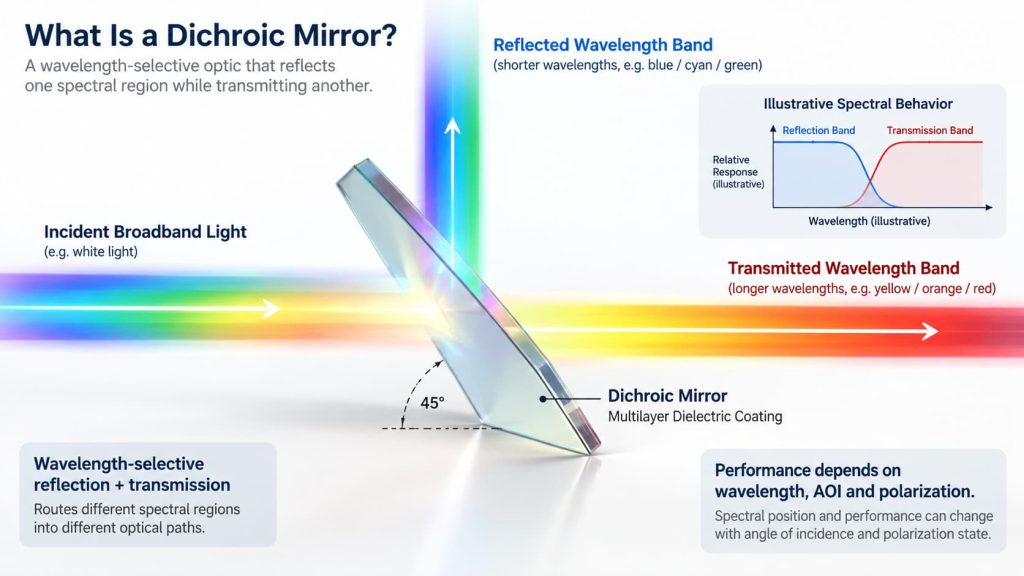
The important engineering point is that a dichroic mirror is not defined only by a nominal wavelength. Its actual behavior depends on the required transmission and reflection bands, angle of incidence, polarization, coating design, substrate and measurement conditions.
How Does a Dichroic Mirror Work?
Most modern dichroic mirrors are based on thin-film interference.
The optical surface contains alternating layers of dielectric materials with different refractive indices. Each interface generates a small reflected wave. By controlling the refractive index and optical thickness of these layers, the coating designer can make reflected waves reinforce one another over selected wavelength regions while allowing other wavelengths to pass through the coating.
The result may look conceptually like this:
Incident broadband light → Dichroic mirror → Selected wavelengths reflected + other wavelengths transmitted
The coating is therefore performing spectral routing rather than simply absorbing unwanted light. In a well-designed dielectric dichroic, most usable optical energy is directed into reflection or transmission, although real components still have absorption, scattering and other losses.
A dichroic coating can be designed with longpass-like, shortpass-like or more complex multiband characteristics. The appropriate response depends on the optical architecture rather than on the name of the component alone.
Reflect Short Wavelengths or Long Wavelengths?
A common misconception is that a dichroic mirror must always reflect short wavelengths and transmit long wavelengths.
That configuration is common, particularly in fluorescence microscopy, but it is not a universal rule.
For example, a longpass-type fluorescence dichroic may reflect a shorter-wavelength excitation band toward the specimen while transmitting longer-wavelength fluorescence toward the detector. Nikon’s description of a reflected-light fluorescence system shows exactly this arrangement: the excitation filter selects the illumination band, the dichroic redirects it toward the sample, and the longer-wavelength fluorescence subsequently passes through the dichroic toward the emission filter and detector.
The reverse optical behavior can also be designed when the system requires it.
Therefore, an engineering specification should state:
Reflection band: wavelengths that must be reflected
Transmission band: wavelengths that must be transmitted
Descriptions such as only “500 nm dichroic mirror” are often incomplete.
Dichroic Mirror vs Ordinary Mirror
An ordinary dielectric or metallic mirror is normally selected because high reflectance is required over a specified wavelength range.
A dichroic mirror has a different job: its reflection characteristics change substantially between selected wavelength regions. RP Photonics defines this class of mirror by significantly different reflection or transmission properties at different wavelengths.
| Feature | Conventional Mirror | Dichroic Mirror |
|---|---|---|
| Main function | Reflect light | Separate/combine wavelengths |
| Spectral behavior | Usually high reflection across target band | High reflection in one region and high transmission in another |
| Typical coating | Metal or dielectric | Usually multilayer dielectric |
| Transmission | Often secondary | Usually an intentional optical path |
| AOI sensitivity | Depends on design | Often critical |
| Typical use | Beam steering | Spectral beam routing |
This difference also explains why a dichroic mirror should not be specified simply as a “high-reflection mirror.”
Dichroic Mirror vs Beamsplitter
A dichroic mirror is technically a type of beamsplitting optic, but it separates optical power primarily according to wavelength.
A conventional non-polarizing beamsplitter may be specified to divide approximately the same wavelength band into a certain transmission/reflection ratio, such as T:R.
A dichroic beamsplitter instead has a spectral requirement such as:
Band A → reflect
Band B → transmit
The distinction matters when preparing specifications. Asking for a “50:50 beamsplitter” describes a very different optical requirement from asking for a dichroic mirror that reflects one wavelength range and transmits another.
GIAI’s current English component structure includes optical filters and beamsplitters as separate engineering product families, while dichroic coatings are also part of the wavelength-selective coating topics used in custom optical projects.
Why Is Angle of Incidence Important?
The angle of incidence, or AOI, is one of the most important parameters of a dichroic mirror.
Many beam-routing systems use the optic near 45° incidence, because this geometry conveniently redirects the reflected beam by approximately 90°. Fluorescence microscopes are a familiar example.
However, multilayer interference coatings are angle-sensitive.
When the AOI changes, the optical phase accumulated within the coating layers also changes. For many dielectric interference designs, increasing the incidence angle shifts spectral features toward shorter wavelengths. The exact amount of shift depends on the multilayer design and optical materials and should therefore be evaluated from the actual coating rather than estimated from a generic value.
This leads to an important specification rule:
A spectrum measured at 0° should not automatically be treated as the spectrum at 45°.
GIAI’s project-level quality reference likewise requires AOI to be defined when wavelength-selective coatings are evaluated, because spectral position can change with incidence angle.
Polarization Also Matters at Oblique Incidence
At normal incidence, polarization effects may be relatively small for many designs. At substantial AOI, however, the coating sees s-polarized and p-polarized light differently.
The two polarization states can exhibit different:
- transition wavelengths,
- reflectance,
- transmittance,
- transition slopes,
- phase behavior.
RP Photonics notes that dielectric mirror reflection spectra depend on AOI and, at non-normal incidence, on polarization.
This becomes particularly important in laser systems, polarization-sensitive instruments and dichroics with steep spectral edges.
If the incident beam has a defined polarization state, that information should be included in the specification. If the system uses unpolarized light, performance across both polarization states may still need to be evaluated.
What Is the Transition Edge?
Between the high-reflection and high-transmission regions is a spectral transition region.
This is where the dichroic changes from predominantly reflecting the incident light to predominantly transmitting it, or vice versa.
Depending on the specification, engineers may describe the transition using terms such as:
cut-on wavelength, cut-off wavelength, crossover wavelength, or transition width.
The transition edge is especially important when two useful spectral bands are close together.
Consider a fluorescence system in which the excitation wavelength lies only a short distance from the fluorescence emission band. Moving the dichroic edge too far toward the excitation side can allow unwanted excitation leakage. Moving it too far toward the emission side can discard useful fluorescence.
For that reason, the steepest possible transition is not automatically the only design goal. The transition must be positioned correctly relative to the source spectrum, excitation filter, fluorescence spectrum, emission filter and detector response.
Why Dichroic Mirrors Are Important in Fluorescence Systems
Fluorescence detection illustrates the function particularly well.
A typical epi-fluorescence optical path can be simplified as:
Light source → Excitation filter → Dichroic mirror → Objective → Sample
and on the return path:
Fluorescence → Objective → Dichroic mirror → Emission filter → Detector
The dichroic allows illumination and detection to share much of the same optical path while separating the two spectral regions. Nikon describes excitation filters, dichroic beamsplitters and emission filters as the three main spectral components in this type of fluorescence system.
The dichroic does not, however, replace the emission filter. The emission filter provides additional rejection of excitation leakage and restricts the detector to the useful fluorescence band.
GIAI also maintains a dedicated engineering article on dichroic mirror selection for fluorescence systems, covering spectral matching, AOI, polarization, angular cones and ghost reflections in greater depth.
Other Common Applications of Dichroic Mirrors
The wavelength-routing principle is useful well beyond fluorescence microscopy.
Typical applications include laser beam combining and separation, where different laser wavelengths share part of the same optical path; harmonic separation, where fundamental and frequency-converted wavelengths must be separated; projection and illumination systems, where red, green and blue spectral channels may be combined or separated; multispectral imaging, where wavelength bands are routed toward different cameras or sensors; and optical instruments and sensing systems, where multiple spectral channels need independent detection.
RP Photonics also describes dichroic mirrors being used for combining or separating beams at different wavelengths and for separating pump and generated wavelengths in laser systems.
What Specifications Matter When Selecting a Dichroic Mirror?
A useful dichroic mirror specification normally starts with the optical system, not with the catalog name of the mirror.
The most important parameters commonly include:
| Parameter | Why It Matters |
|---|---|
| Reflection wavelength range | Defines which wavelengths are routed into the reflected path |
| Transmission wavelength range | Defines which wavelengths continue through the optic |
| Reflectance / transmittance targets | Determines optical throughput and separation |
| Transition wavelength | Defines where spectral switching occurs |
| Transition width | Important when adjacent spectral channels are close |
| AOI | Directly affects interference behavior |
| Polarization | Can alter performance at oblique incidence |
| Substrate | Influences transmission, mechanical behavior and finished optic |
| Clear aperture | Defines usable coated optical area |
| Dimensions / thickness | Must match the optical and mechanical assembly |
| Surface requirements | Can matter in imaging or wavefront-sensitive systems |
| Back-surface treatment | Can affect Fresnel reflection and ghost beams |
| Inspection conditions | Ensures the measured spectrum represents the actual application |
GIAI’s controlled engineering reference uses the same project-review logic: wavelength range, transmission, reflection, blocking requirements, substrate, geometry, coating, AOI, polarization and acceptance conditions are defined before the manufacturing and verification route is established.
Back-Surface Reflections Should Not Be Ignored
A dichroic mirror is normally built on a transparent optical substrate because part of the spectrum must pass through it.
That means the second surface of the substrate can also generate a Fresnel reflection.
Depending on the system, this secondary reflection can create:
- ghost images,
- displaced secondary beams,
- stray light,
- detector background,
- interference effects.
A suitable anti-reflection coating on the opposite surface or, in some designs, a slight substrate wedge can help control these effects. RP Photonics specifically notes backside reflection and substrate transmission as considerations in dichroic mirror design.
Whether either measure is required should be determined from the optical layout rather than applied automatically.
Common Dichroic Mirror Selection Mistakes
One common mistake is choosing the component by a single nominal wavelength without defining what should happen on either side of that wavelength. A second is using a normal-incidence spectral curve for a 45° system. Another is ignoring polarization even though the mirror operates at a substantial AOI.
It is also risky to optimize only a peak transmission or peak reflectance value. A system normally needs performance across a wavelength interval, so average or minimum behavior over the actual working band may be more meaningful.
Finally, the dichroic should not be evaluated independently when it is part of a larger filter system. Excitation filters, emission filters, detectors, source spectra and other dichroics can all influence the usable system response.
What Should You Send for a Custom Dichroic Mirror Review?
For a custom optical project, provide enough information to reconstruct the actual optical requirement.
A useful RFQ package should include the required reflection and transmission bands, performance targets in each band, operating AOI, polarization condition, substrate requirement, component dimensions and thickness, clear aperture, coating requirements, optical layout or drawing, quantity, and inspection or acceptance requirements.
If the optic operates over a range of angles rather than one fixed AOI, that angular range should also be specified.
GIAI reviews custom optical projects against drawings, samples, optical requirements, substrate, geometry, coating conditions and inspection criteria before defining the manufacturing route. The company reference specifically cautions against treating a theoretical coating capability as proof of an unverified numerical performance limit.
Conclusion
So, what is a dichroic mirror?
It is a wavelength-selective optical mirror that uses a dielectric interference coating to route different spectral regions into different optical paths. One wavelength band may be reflected while another is transmitted, allowing the component to separate or combine light without relying primarily on absorption.
For engineering applications, however, the definition is only the starting point. The performance of a dichroic mirror must be considered together with its reflection band, transmission band, transition edge, AOI, polarization, substrate, beam geometry and inspection conditions.
The best component is therefore not simply the dichroic mirror with the highest quoted reflectance or transmission. It is the one whose measured spectral behavior matches the actual optical system.
Frequently Asked Questions
Is a dichroic mirror the same as a beamsplitter?
A dichroic mirror is a type of beamsplitting optic, but it primarily divides light according to wavelength. A conventional beamsplitter may instead divide substantially the same spectral region according to an optical power ratio.
Does a dichroic mirror absorb unwanted wavelengths?
Its primary function is normally interference-based reflection and transmission rather than absorption. Real components still have some absorption and scattering losses.
Why are many dichroic mirrors used at 45°?
A 45° geometry allows the reflected beam to be redirected by approximately 90°, which is convenient in fluorescence, imaging and beam-combining systems. The coating must nevertheless be designed and characterized for the intended AOI.
Does changing the angle change the spectrum?
Yes. Dielectric interference coatings are angle-sensitive. Increasing AOI generally shifts spectral features toward shorter wavelengths, while oblique incidence can also create different responses for s and p polarization.
Can one dichroic mirror separate more than two wavelength regions?
Yes. More complex multilayer coatings can provide several reflection and transmission regions. These are often described as multiband, polychroic or polychromatic mirrors.
