
Technical Resources
NIR Bandpass Filter for Machine Vision: Selection Guide
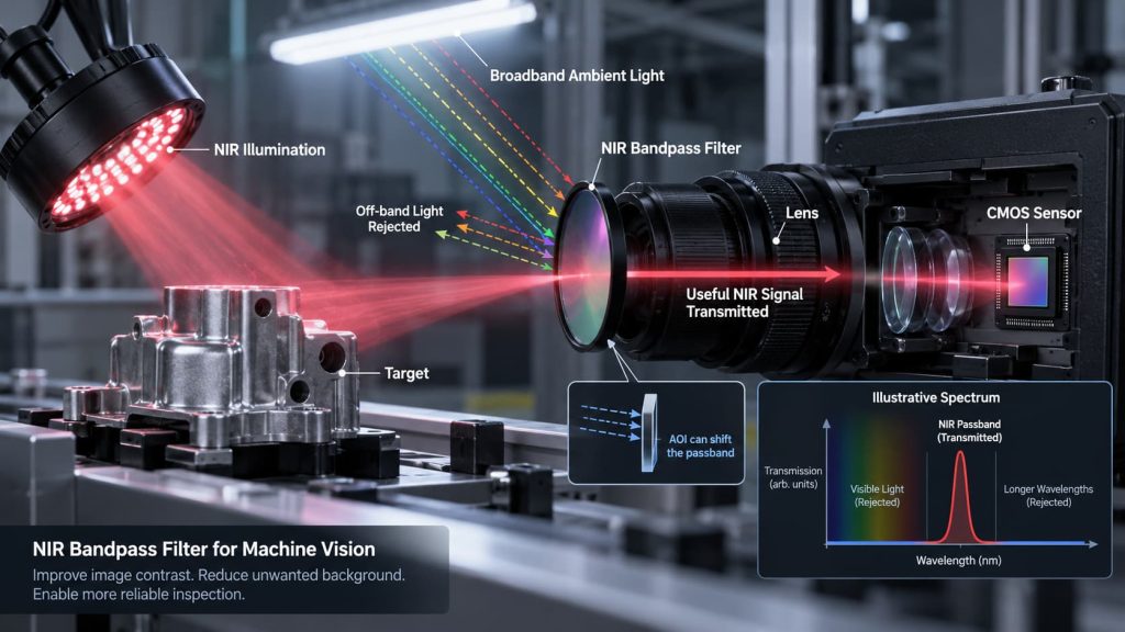
A machine vision system may use an 850 nm or 940 nm LED, a monochrome camera with good near-infrared sensitivity, and stable exposure settings—yet still produce images whose contrast changes with factory lighting, sunlight, or reflections from nearby equipment.
The problem is often not the camera alone. The detector is receiving both the useful NIR illumination and unwanted optical background.
An NIR bandpass filter for machine vision is used to restrict the spectrum reaching the camera so that wavelengths around the intended near-infrared signal are transmitted while much of the off-band radiation is attenuated. The objective is not simply to “block visible light.” It is to improve the ratio between useful optical signal and unwanted background.
That distinction matters because the correct filter cannot be selected from a nominal wavelength such as “850 nm” alone.
What Does an NIR Bandpass Filter Actually Do in a Machine Vision System?
A useful way to think about an NIR inspection system is as a complete spectral chain:
Illumination → target → optical filter → imaging optics → image sensor
At any wavelength, the signal reaching the camera depends on several factors simultaneously:
source output × target reflectance or transmission × filter transmission × lens transmission × sensor responsivity
The filter only controls one part of this chain.
Suppose an inspection station illuminates a component with an NIR LED. Without spectral filtering, the camera can also receive fluorescent lighting, visible reflections, sunlight, neighboring machine lights, and other near-infrared radiation. If these unwanted components vary during production, the image histogram and feature contrast can move even when the part itself has not changed.
A bandpass filter restricts the camera to a defined wavelength interval around the useful illumination. This can make thresholding, edge detection, feature recognition, positioning, or measurement more repeatable.
However, it does not remove unwanted radiation that falls inside the same passband. Strong sunlight containing energy near the selected wavelength, for example, can still reach the sensor.
Why NIR Is Useful for Machine Vision
Silicon image sensors can retain significant sensitivity beyond the visible spectrum, and some industrial sensors are specifically designed to improve NIR response. Sony, for example, highlights enhanced sensitivity at 850 nm in its IMX900 industrial global-shutter sensor, while its industrial ToF sensor portfolio includes recommended illumination wavelengths such as 850 nm, 905 nm, and 940 nm.
This makes NIR illumination useful when the inspection does not depend on visible color information.
More importantly, objects do not necessarily have the same reflectance in NIR as they do in visible light. Two surfaces that look similar to the human eye may produce different contrast under near-infrared illumination. Conversely, printed marks or materials that are highly visible under white light may lose contrast in NIR.
For this reason, wavelength selection should ideally begin with the actual production sample, not with a general assumption that NIR will automatically produce a better image.
The Six Specifications That Matter Most
Center Wavelength: Match the Source, Not Just Its Label
Center wavelength, or CWL, defines the spectral position of the bandpass filter.
If the illumination is labeled 850 nm, it may be tempting to specify only:
CWL = 850 nm
That is incomplete.
The actual LED emission spectrum has finite width, and its spectral distribution can change with operating conditions such as junction temperature and drive current. The correct filter should therefore be evaluated against the actual source spectrum, preferably using manufacturer spectral data or measured illumination.
The same principle applies to 940 nm illumination, laser sources, VCSELs, structured-light systems, and other active NIR emitters.
The filter and light source must overlap under the conditions in which the machine will actually operate.
FWHM: Narrower Is Not Automatically Better
Full width at half maximum, or FWHM, describes the width of the transmitted band.
A narrower passband can reject more off-band optical background. But reducing bandwidth also reduces tolerance for changes in the rest of the optical system.
An excessively narrow filter may begin cutting into the useful signal because of source spectral width, source wavelength shift, manufacturing tolerance, filter temperature behavior, or angle-of-incidence effects.
A wider passband gives the system more spectral margin but allows more unwanted light to reach the sensor.
The engineering question is therefore not:
“What is the narrowest filter available?”
It is:
“What is the narrowest passband that still contains the required signal under the full range of operating conditions?”
That is a much more useful specification rule.
Passband Transmission: Evaluate the Whole Useful Band
Peak transmission is easy to quote, but it does not necessarily describe the signal delivered to the camera.
A source does not usually emit all of its optical power at one infinitely narrow wavelength. If the LED spectrum occupies a finite band, the relevant quantity is the overlap between the source spectrum and the complete filter transmission curve.
A filter with a high peak at CWL can still lose useful optical power if its transmission falls rapidly across significant portions of the illumination spectrum.
For machine vision, engineers should therefore evaluate the transmission profile across the usable source band, not only the maximum transmission number.
Blocking Range and Optical Density
Good passband transmission does not guarantee good ambient-light rejection.
The wavelengths outside the passband also matter.
Optical density is commonly expressed as:
OD = −log10(T)
where T is fractional transmission.
For reference, OD3 corresponds to 0.1% transmission and OD4 to 0.01%. But stating “OD4” by itself still does not fully define a filter. The wavelength interval over which the blocking requirement applies must also be specified.
The required blocking range should be considered together with the spectral response of the camera.
If the detector remains sensitive at wavelengths far from the target NIR band, leakage in those regions can still contribute background even though the filter appears well blocked immediately beside the passband.
This is why a practical requirement looks more like:
target passband + required transmission + blocking wavelength interval + required OD
rather than simply:
“850 nm bandpass filter.”
Angle of Incidence
Angle of incidence is one of the most important—and frequently overlooked—parameters for interference bandpass filters.
As AOI increases, the spectral response of an interference filter generally moves toward shorter wavelengths. In an imaging system, this becomes more complicated because light from different field points can reach the filter at different angles.
Edmund Optics specifically notes this issue in machine vision: when an interference filter is mounted in front of a lens, wide-angle optical systems can expose the filter to a larger angular distribution, producing progressively greater spectral blue shift away from the nominal design condition.
This means that a filter measured at normal incidence should not automatically be assumed to deliver the same spectral response when installed in front of a wide-field lens.
For compact machine vision systems, the RFQ should therefore define not only nominal AOI but, where possible, the expected range of incident angles or relevant lens geometry.
Mechanical Integration
Spectral performance is only part of the specification.
Diameter or rectangular dimensions, thickness, clear aperture, coated area, edge geometry, mounting method, and mechanical tolerance can all affect integration.
A filter with the correct spectrum can still create problems if the clear aperture is too small and causes vignetting, if the mounting geometry tilts the filter unintentionally, or if the optical stack places the filter in a strongly converging beam.
Spectral design and mechanical design should therefore be reviewed together.
850 nm vs 940 nm for Machine Vision
There is no universal rule that 850 nm is better than 940 nm, or vice versa.
| Engineering factor | 850 nm | 940 nm |
|---|---|---|
| Industrial sensor compatibility | Commonly supported; some industrial sensors specifically optimize NIR response around 850 nm | Also widely used, especially in active sensing and ToF architectures |
| Sensor responsivity | Must be checked from the specific camera or sensor QE curve | Must be checked separately; do not assume the same response as 850 nm |
| Illumination matching | Requires an 850 nm-compatible passband | Requires a 940 nm-compatible passband |
| Typical design concern | Background light, source/filter overlap, AOI | Sensor sensitivity, source/filter overlap, AOI |
| Selection basis | Target contrast + source + sensor + environment | Target contrast + source + sensor + environment |
Sony’s industrial imaging portfolio illustrates why the wavelength cannot be chosen independently from the detector: its IMX900 emphasizes enhanced 850 nm response, while other sensing architectures explicitly support 940 nm illumination. Sony’s RGB-IR IMX775, for example, is designed for 940 nm NIR imaging.
The practical procedure is therefore to compare the illumination spectrum and the sensor QE or spectral-response curve on the same wavelength axis.
Do not assume that changing an 850 nm illuminator to 940 nm requires only changing the LEDs. The filter and camera response need to be reviewed as well.
When an NIR Bandpass Filter Helps—and When It Does Not
An NIR bandpass filter is particularly useful when a machine vision system has a controlled, wavelength-specific illuminator and unwanted background exists outside that wavelength range.
This is different from broad NIR imaging.
If useful material contrast exists across a large portion of the NIR spectrum, restricting the camera to a narrow band can discard valuable photons. In that situation, a longpass filter or another spectral architecture may be more appropriate.
The broader selection logic is discussed in GIAI’s related guide, Bandpass vs Longpass Filter for Machine Vision.
Bandpass filtering also cannot correct every imaging problem. If glare comes from the NIR illuminator itself, the reflected glare is still inside the passband. Polarization, illumination geometry, diffuse lighting, or changes in viewing angle may be required.
Similarly, if the camera includes an internal IR-cut filter, installing an external NIR bandpass filter will not restore wavelengths already rejected by the camera’s optical stack.
The complete camera assembly must be checked.
Wide-Angle Lenses Can Change the Effective Passband
This deserves particular attention in compact systems.
Imagine an NIR filter mounted directly in front of a short-focal-length lens. On-axis rays may strike the filter close to normal incidence, while rays from the edge of the field arrive at a larger angle.
The result is not necessarily one uniform shifted spectrum.
Different field points can experience different effective spectral responses.
In a narrowband system, this can appear as uneven image brightness across the field even when ordinary lens shading correction is already applied. The cause may be spectral rather than purely geometric.
Before tightening FWHM to improve ambient-light rejection, check whether the optical design exposes the filter to a broad AOI distribution. A very narrow filter combined with a wide-angle lens can make the system more sensitive to this effect.
How to Specify an NIR Bandpass Filter for Machine Vision
A useful filter specification begins with the system rather than the component.
Start by identifying the illumination wavelength and its actual spectral distribution. Then determine where the production sample produces the required optical contrast and compare that with the spectral sensitivity of the camera.
From there, define the passband, FWHM, transmission requirement, blocking range, and OD. Add the real AOI and optical geometry rather than assuming normal incidence by default.
Mechanical information should include filter dimensions, thickness, clear aperture, and installation constraints. If temperature, outdoor operation, vibration, or other environmental conditions are relevant, those conditions should be included in the engineering review as well.
Finally, specify how spectral acceptance will be verified.
For wavelength-selective components, visual appearance is not a substitute for spectral measurement. GIAI’s internal manufacturing and quality framework treats transmission, blocking, CWL, FWHM, OD, AOI, dimensions, and project-defined acceptance criteria as specification-dependent verification items rather than universal values.
Common Specification Mistakes
A filter request such as “Need an 850 nm machine vision filter” leaves several important questions unanswered.
What is the LED spectrum? How wide can the passband be? Which wavelengths need blocking? What OD is required over those wavelengths? What camera sensor is being used? Is there an existing IR-cut element? What AOI will the filter experience? Is the filter in front of a wide-angle lens? What dimensions and clear aperture are required?
Another common mistake is copying one existing filter specification into a different system.
A CWL, FWHM, transmission value, or OD demonstrated by one product should not be treated as a universal specification for every NIR bandpass filter. GIAI’s controlled content rules explicitly distinguish product-specific parameters from general company capability.
The correct filter is the one whose spectrum remains compatible with the source, target, detector, and optical geometry of the actual machine.
Custom NIR Bandpass Filter Review at GIAI
GIAI Photonics supports optical filters, infrared optics, optical coating, and project-specific inspection within its current custom-optics manufacturing scope. Projects may be evaluated from drawings, optical specifications, or existing samples.
For an NIR machine vision project, useful technical input includes the illumination wavelength or source spectrum, required CWL and FWHM if already defined, transmission target, blocking wavelength range and OD, camera or sensor information, AOI, filter dimensions, substrate requirements if specified, operating environment, quantity, and inspection criteria.
GIAI also currently lists a dedicated machine-vision NIR bandpass product example, the Machine Vision BP880 Bandpass Filter. Product-specific spectral values should be treated as parameters of that particular product rather than general limits for all custom filters.
Conclusion
An NIR bandpass filter for machine vision should not be selected by wavelength alone.
The center wavelength must match the illumination. FWHM must balance background rejection against spectral tolerance. Blocking must be specified over the wavelength range that matters to the detector. AOI must reflect the real optical geometry, especially with wide-angle lenses. Sensor response must be evaluated together with the source spectrum rather than treated as an independent camera specification.
When those parameters are considered as one optical system, an NIR bandpass filter can substantially improve the stability of active-illumination machine vision. When they are specified independently, even a filter with an apparently excellent transmission curve may underperform after installation.
FAQ
What FWHM is best for an NIR machine vision filter?
There is no universal optimum. The passband should be wide enough to contain the useful source spectrum plus expected wavelength shifts and tolerances, while remaining narrow enough to reject unwanted background.
Can the same bandpass filter be used with both 850 nm and 940 nm illumination?
Normally not if the filter is designed as a narrow single-band filter. The passband must overlap the illumination wavelength. A different filter architecture would be required if both bands need to be transmitted.
Does an NIR bandpass filter completely eliminate sunlight interference?
No. It attenuates wavelengths outside the passband, but sunlight or other sources containing energy inside the transmitted band can still reach the sensor.
Why can a bandpass filter work on the bench but change after installation?
One common reason is angle of incidence. Interference filters can shift toward shorter wavelengths when used away from their design AOI, and wide-angle imaging systems may expose the filter to a range of angles across the field.
