
Technical Resources
Absorptive vs Reflective Neutral Density Filters: Key Differences
Absorptive and reflective neutral density (ND) filters both reduce light intensity, but they manage rejected optical energy differently. Absorptive ND filters primarily convert light energy into heat within an absorbing material, whereas reflective ND filters redirect a portion of the incident light using an optical coating. Absorptive designs often help minimize back-reflection; reflective designs can provide relatively flat attenuation across broad wavelength ranges. The better option depends on wavelength, optical density, unwanted reflections, power handling and the geometry of the optical system.
What Is the Difference Between Absorptive and Reflective ND Filters?
A neutral density filter attenuates light across a specified spectral range while aiming to preserve the relative spectral distribution. Unlike a bandpass filter, an ND filter is primarily intended to control intensity rather than select a narrow wavelength interval.
Absorptive Neutral Density Filters
A conventional absorptive ND filter uses optical glass containing absorbing constituents. As the light propagates through the glass, a portion of its optical energy is absorbed. Other absorptive constructions also exist, including absorbing thin-film designs, so the exact mechanism should be confirmed from the component specification.
For bulk absorbing material, the Beer–Lambert relationship approximates internal transmittance as:
Increasing the optical path length generally increases absorption. However, because the absorption coefficient depends on wavelength, a glass described as neutral over the visible region may not provide the same attenuation in the ultraviolet or infrared.
Absorptive filters tend to produce less unwanted back-reflection than many reflective metallic ND filters, but they are not inherently reflection-free. Uncoated glass surfaces can still generate Fresnel reflections.
Reflective Neutral Density Filters
Reflective ND filters use an optical coating to reduce transmitted intensity. Metallic thin films are common, although other engineered coating constructions are possible. A metallic coating typically both reflects and absorbs incident light.
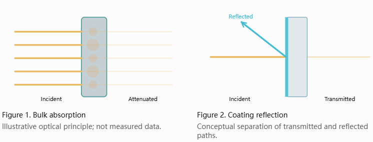
Therefore, light that does not pass through a reflective ND filter is not necessarily reflected in full. A coating may absorb a meaningful portion of the incident power, particularly under high irradiance.
Metal-based designs can achieve substantial attenuation in a relatively thin component and may offer broad spectral neutrality. Their main system-level drawback is reflected light, which can produce optical feedback, ghost images or stray-light paths.
Absorptive vs Reflective Neutral Density Filters: Key Comparison
| Engineering factor | Absorptive ND filter | Reflective ND filter |
|---|---|---|
| Main attenuation mechanism | Absorption in glass or an absorbing layer | Coating reflection combined with absorption |
| Typical construction | Absorbing optical glass | Coated optical substrate |
| Back-reflection | Often relatively low, but not zero | Can be significant; depends on coating |
| Spectral uniformity | Depends on material, thickness and wavelength | May be relatively flat over a broad design band |
| Heating | Energy absorbed within the material | Absorption can be concentrated in the coating |
| High-power suitability | Limited by bulk heating, stress and damage | Limited by coating heating and damage |
| Angle of incidence | Changes optical path length and surface reflection | Changes coating response and polarization behavior |
| Primary design concern | Thermal load and spectral dependence | Optical feedback, stray reflection and coating limits |
The table describes typical design tendencies rather than guaranteed specifications. Actual transmission, reflection and thermal limits must be evaluated for the selected filter.
How Does Optical Density Relate to Transmission?
Both absorptive and reflective ND filters are commonly specified by optical density (OD). OD describes attenuation in the transmitted beam, regardless of whether the removed energy is absorbed or reflected.
T = 10−ODT is fractional optical transmittance, not percentage transmittance.
| Optical density | Ideal transmission | Attenuation factor |
|---|---|---|
| OD 0.3 | 50.12% | Approximately 2× |
| OD 0.5 | 31.62% | Approximately 3.16× |
| OD 1.0 | 10% | 10× |
| OD 2.0 | 1% | 100× |
| OD 3.0 | 0.1% | 1,000× |
| OD 4.0 | 0.01% | 10,000× |
For example, a hypothetical OD 1.0 filter receiving 100 mW of incident light transmits 10 mW under the stated measurement conditions. The other 90 mW leaves the forward transmitted beam, but it may be absorbed, reflected or divided between those mechanisms.
These are calculated examples, not measured results or universal performance specifications for GIAI products.
Why Spectral Neutrality Matters
The name neutral density does not mean the transmission is exactly constant at all wavelengths. Actual neutrality is limited to a defined spectral interval and tolerance.
Absorptive Glass: Wavelength-Dependent Absorption
An absorbing material has a wavelength-dependent absorption coefficient. Even if its transmission appears relatively flat in visible light, the attenuation may increase or decrease toward the ultraviolet or infrared edges of the design range. Material grade and thickness also matter.
Reflective Coatings: Broadband, but Not Perfectly Flat
Metallic films can offer relatively uniform broadband attenuation. Nevertheless, their optical constants, thickness, substrate and coating structure influence the transmission curve. Some designs can also exhibit interference-related spectral features.
For a multispectral sensor, a broad-spectrum source or an imaging system with demanding color accuracy, specify transmission or OD across the entire operating wavelength range, not merely at one reference wavelength. Consider the source spectrum and detector spectral sensitivity together.
Back-Reflection and Stray Light: Which Filter Is Safer for the Optical Path?
In systems sensitive to reflected light, the amount and direction of reflection may be as important as transmitted attenuation.
Laser and Coherent-Light Systems
A reflective ND filter can send some light toward the laser source. Depending on the source design, this optical feedback may disturb stability. Parallel reflective filters can also form unwanted resonant cavities under coherent illumination.
Potential system-level controls include suitable filter tilt, optical isolation, beam dumps and careful spacing. However, tilting changes the angle of incidence and may alter transmission and polarization response. Every mitigation must therefore be checked against the complete optical layout.
Machine Vision and Imaging Systems
Stray reflections between the ND filter, lens surfaces and sensor cover glass may cause ghosts, flare or background light. An absorptive design can be helpful where these paths are difficult to manage, although surface reflections and the need for baffling remain.
Selection rule: If back-reflection is a critical system constraint, request a reflectance or return-loss requirement in addition to the OD specification.
Thermal Load: Does a Reflective ND Filter Handle More Power?
Not necessarily. A reflective filter may redirect some power away from the component, but another portion can be absorbed by its coating. The resulting localized heating may limit performance even when average absorbed power appears modest.
Heat in Absorptive ND Filters
Bulk absorption can create temperature gradients, thermally induced refractive-index changes, stress and possible damage. The severity depends on beam power, illuminated area, exposure time, substrate properties and mounting conditions.
Heat in Reflective ND Filters
Absorption within a thin coating may generate concentrated surface heating. High peak intensities or pulse fluence can cause damage even when the average power is not particularly high. Metallic coatings may also be sensitive to prolonged thermal exposure and handling.
For laser systems, evaluate wavelength, continuous-wave or pulsed operation, average and peak power, pulse width, repetition rate, beam diameter, AOI, thermal management and the applicable damage specification. Neither ND type should be assumed suitable for high-power laser exposure solely on the basis of OD.
An ordinary ND filter is not a substitute for rated laser safety eyewear or an appropriately engineered laser beam attenuator.
Does the Angle of Incidence Affect ND Filter Performance?
Yes. Both filter types may change behavior at oblique incidence, but for different reasons.
Absorptive Filters
For a plane-parallel bulk absorbing plate, the path length inside the material increases as the refracted ray becomes more oblique:
This can increase absorption. At the same time, Fresnel reflection at the entry and exit surfaces changes with angle and polarization. Overall transmission depends on both effects.
Reflective Filters
AOI changes the boundary conditions at the coating. The transmittance and reflectance of s- and p-polarized light may differ, especially at larger angles. Optical systems using converging or diverging beams may illuminate the filter over a range of angles, so normal-incidence measurements alone may be insufficient.
Can Multiple Neutral Density Filters Be Stacked?
For sequential filters with independent transmissions and negligible multiple-reflection or interference effects, total OD is additive:
For example, OD 0.5 and OD 1.0 nominally combine to OD 1.5, equivalent to approximately 3.16% transmission. This approximation may fail for closely spaced reflective filters illuminated by coherent light, because multiple reflections can introduce resonant behavior.
If filters must be stacked, review spacing, orientation, reflected-beam paths and measured total transmission. Do not simply add the catalog OD values without considering the installation conditions.
How to Choose Between Absorptive and Reflective ND Filters
| Application requirement | Useful starting point | Verify before selection |
|---|---|---|
| Minimize return light to a laser | Consider absorptive or other low-reflection attenuation | Return loss, heat and laser power compatibility |
| Reduce camera illumination | Either design may be appropriate | Image artifacts, spectral neutrality and AOI |
| Attenuate broadband measurements | Prioritize spectral flatness | Transmission spectrum and uncertainty |
| Photometric calibration | Choose a characterized attenuation standard | Calibration wavelength, traceability and uncertainty |
| High-power laser application | Evaluate purpose-designed attenuation hardware | Absorption, beam geometry and damage limits |
| Compact sensing module | Compare both optical and mechanical constraints | Thermal loading, reflected light and aperture |
- Define wavelength and source spectrum. Identify single-wavelength, multiwavelength or broadband operation.
- Calculate the required OD. Use incident power and the acceptable downstream intensity.
- Identify reflection-sensitive paths. Consider lasers, nearby sensors and imaging surfaces.
- Check power and heat. Evaluate absorbed energy, beam size, pulse characteristics and mounting.
- Specify geometry. Include AOI, angular spread, clear aperture and polarization where relevant.
- Verify the selected component. Request spectral transmission data, suitable reflection information and applicable inspection criteria.
Common Mistakes When Specifying ND Filters
Assuming a Single OD Value Applies at Every Wavelength
A nominal OD may only be specified at one reference wavelength or within a limited range. Request spectral OD or transmission data across the wavelengths used by the system.
Assuming Reflective Filters Do Not Produce Heat
Metallic coatings commonly absorb part of the incident power. Confirm power handling and coating suitability rather than assuming all rejected light is reflected.
Ignoring Optical Feedback
Reflected power can enter a laser or another optical path. Establish an acceptable reflectance limit and manage the reflected-beam direction.
Using ND as a Laser Safety Rating
Optical density alone does not establish damage resistance or safe viewing conditions. Laser safety components require their own applicable specifications and controls.
Measuring Only at Normal Incidence
Actual installed AOI, polarization and beam divergence can alter measured attenuation. Test the conditions that matter for the finished system.
How Should ND Filter Performance Be Verified?
Acceptance criteria should be linked to the intended operating conditions. Depending on the design, verification may address wavelength-dependent transmission, OD tolerance, reflection, clear aperture, thickness, surface condition and uniformity.
Distinguish internal transmittance, which excludes surface reflection losses, from total component transmittance. A bulk-glass calculation alone may not predict the transmission of the finished, coated or uncoated part.
For precision measurement or calibration, specify the measurement geometry, calibration reference and required uncertainty separately from ordinary production inspection. A certificate or curve measured under one optical arrangement does not automatically describe every installed configuration.
What to Include in a Custom ND Filter Specification
| Parameter | What the engineering team needs |
|---|---|
| Filter function | Attenuation, calibration, imaging or detector control |
| Construction preference | Absorptive, reflective, low-reflection or open for review |
| Wavelength | Single wavelength or full operating spectral interval |
| Optical density | Target OD or transmission and tolerance |
| Spectral neutrality | Acceptable variation across the operating range |
| Reflection | Maximum return reflection if relevant |
| Beam conditions | CW/pulsed, average or peak power, beam size and pulse details |
| Geometry | AOI, angle distribution, clear aperture and polarization |
| Mechanical | Dimensions, thickness, mounting and surface requirements |
| Inspection | Measurement method, report format and acceptance criteria |
| Project details | Drawing or sample, quantity and operating environment |
Neutral Density Filter Projects at GIAI Photonics
GIAI Photonics supports precision optical components and custom optics projects involving optical filters, substrates, coatings, fabrication and inspection. Its existing Fixed Neutral Density Filters page provides a starting point for discussing attenuation applications.
For a particular absorptive, reflective or low-reflection ND design, feasibility and performance must be confirmed against the actual drawing and optical requirements; a general product listing does not guarantee every construction or specification.
Engineers can also explore the Optical Filters range and the Quality Assurance approach used to define project-specific verification.
To request a technical review, provide the working wavelength range, target OD, power and reflection constraints, AOI, substrate preference, dimensions, quantity and inspection requirements through the GIAI Photonics contact page.
Frequently Asked Questions
Which is better: an absorptive or reflective ND filter?
Neither is universally better. Absorptive designs are often useful when unwanted back-reflection is a major concern. Reflective designs can offer broad spectral attenuation but may introduce reflected-light paths. Compare the actual transmission spectrum, reflection, power limits and installed geometry.
Do reflective neutral density filters absorb light?
Yes. A metallic ND coating generally both reflects and absorbs incident light. The absorbed portion may generate localized heating, so reflective construction does not automatically mean higher power handling.
Are absorptive ND filters completely non-reflective?
No. Even bulk absorbing glass has surface reflections, depending on refractive index, AOI, polarization and coating. If return light is critical, specify and verify the allowable reflectance.
Can a reflective ND filter be used with a laser?
Possibly, if its wavelength range, damage limits and reflection behavior are suitable. Optical feedback and high-intensity absorption require particular attention. ND is not itself a laser safety rating.
Can ND filters change the color of transmitted light?
Yes. Real ND filters may not attenuate every wavelength equally. When transmission varies over the source and detector operating bands, relative spectral distribution and measured color can change.
What specifications matter most when ordering an ND filter?
Begin with optical density and operating wavelength range, then specify tolerance, AOI, reflection, incident power, dimensions and inspection conditions as required by the application.
Conclusion
Absorptive and reflective neutral density filters perform the same basic attenuation function through different physical mechanisms. Absorptive filters predominantly dissipate energy in absorbing material and may reduce back-reflection problems. Reflective filters redirect a portion of the light, while still potentially absorbing energy in the coating.
Choose by system requirements rather than filter type alone: wavelength-dependent attenuation, unwanted reflection, thermal load, angle of incidence and verification conditions should all be considered before finalizing the optical design.