
Technical Resources
Wavefront Distortion in Optical Lenses: Meaning & Effects
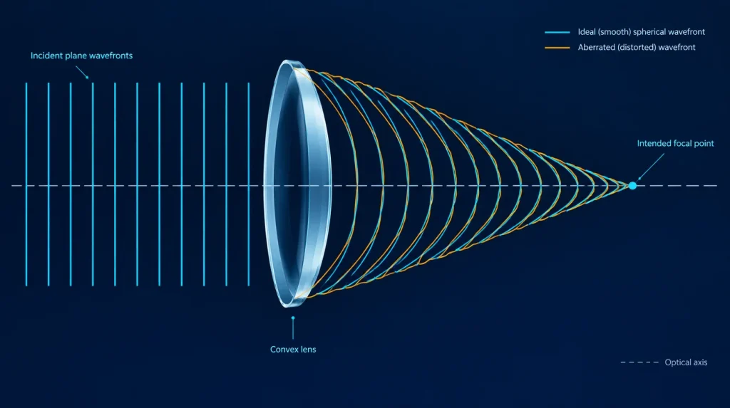
Wavefront distortion in an optical lens means that the light emerging from the lens no longer has exactly the wavefront shape intended by the optical design. Instead of converging toward an ideal focal point, different portions of the beam can experience different optical path errors, potentially reducing image sharpness, focus quality, and optical system performance.
In optical engineering, this departure is commonly described as wavefront error (WFE) or wavefront aberration. It is an important way to evaluate lenses used in imaging, laser focusing, optical sensing, and precision instrumentation.
A lens may appear clear, correctly shaped, and free of visible scratches while still introducing measurable wavefront error. Understanding this distinction is essential when specifying or inspecting precision optical components.
What Is an Optical Wavefront?
A wavefront is an imaginary surface connecting points of equal phase in a propagating optical wave. Its shape indicates how light travels through an optical system.
For a collimated beam, the ideal wavefront is planar. When that beam passes through an ideal converging lens, the transmitted wavefront becomes spherical, converging toward the intended focal point.
A real lens may produce a slightly different wavefront because of optical design aberrations, manufacturing deviations, material properties, or mechanical conditions.
The difference between the actual wavefront and the intended reference wavefront is the wavefront error.
How Does Wavefront Distortion Occur in a Lens?
Several factors can contribute to wavefront distortion. Some originate in the optical design, while others arise during fabrication, assembly, or operation.
1. Optical surface form errors
A lens surface is manufactured to a defined spherical, aspherical, or other nominal geometry. Small departures from that geometry can change the optical path through the lens.
These departures may create defocus, astigmatism, spherical aberration, or other wavefront components. Their effects depend on the shape and spatial distribution of the surface error.
2. Refractive-index inhomogeneity
Light travels through an optical material according to its refractive index. If the index varies across the lens material, different portions of the transmitted beam can accumulate different optical path lengths.
Consequently, even surfaces that meet their individual form specifications do not necessarily guarantee a low transmitted wavefront error.
3. Lens decentration and alignment errors
A lens installed away from its intended optical axis, or tilted relative to the beam, can introduce additional aberrations.
The resulting performance may differ significantly from the nominal design, particularly in multi-element imaging assemblies or tightly aligned laser systems.
4. Mechanical mounting stress
Excessive clamping pressure, adhesive shrinkage, or thermal expansion mismatch can deform a lens or produce stress-related refractive-index changes.
A lens that performs well before mounting may therefore exhibit additional wavefront error after installation.
For more detail, see How Lens Mounting Stress Affects Optical Performance .
5. Operating wavelength and temperature
Lens performance depends on wavelength because refractive index and optical aberrations are generally wavelength-dependent. Temperature changes can also modify lens dimensions, refractive index, and mechanical alignment.
A wavefront measurement at one wavelength and temperature should not automatically be treated as representative of every operating condition.
How Does Wavefront Distortion Affect Image Quality?
Wavefront distortion changes the phase relationship among light waves reaching the image plane. This can redistribute optical energy away from the intended image point and change the structure of the focal spot.
The practical effects depend on the aberration type, its magnitude, and the optical system.
Reduced focal spot quality
In a diffraction-limited system, a point source produces a characteristic diffraction pattern. Wavefront errors can spread energy away from the central peak, broaden or reshape the focal spot, and reduce peak intensity.
This is especially important in laser focusing and optical systems that require concentrated energy within a small region.
Lower image contrast and resolution
Wavefront aberrations can alter the point spread function (PSF) and modulation transfer function (MTF).
As a result, fine image details may lose contrast even when the lens appears mechanically acceptable.
However, one RMS wavefront value does not uniquely determine the complete MTF. Two wavefronts with similar RMS errors can have different spatial aberration patterns and different imaging consequences.
Different aberration patterns
| Aberration | Typical Optical Effect |
|---|---|
| Spherical aberration | Rays from different pupil zones do not focus at the same axial position. |
| Coma | Off-axis point images may develop asymmetric, comet-like shapes. |
| Astigmatism | Different meridional planes focus at different positions. |
| Defocus | The observation plane differs from the best-focus position. |
Defocus is an important special case. If the optical system permits refocusing, part of the observed wavefront error may be correctable through axial adjustment. Other aberrations generally require different corrections.
Is Wavefront Distortion the Same as Image Distortion?
No. Although both terms contain the word “distortion,” they describe different optical characteristics.
Wavefront distortion concerns departures of optical phase from the intended wavefront and may affect image sharpness or focal energy distribution.
Geometric image distortion describes a change in image magnification or position across the field of view. Barrel and pincushion distortion are common examples.
A lens can exhibit geometric distortion while maintaining relatively sharp local image points. Conversely, it can have substantial wavefront aberrations and produce blurred images without obvious barrel or pincushion distortion.
The distinction matters because wavefront testing and geometric distortion calibration do not measure the same property.
How Is Wavefront Distortion Measured?
Wavefront error is commonly characterized using interferometry. In a suitable test configuration, an interferometer compares the wavefront produced by the optical component with a reference wavefront.
The resulting interference data can be processed to create a wavefront error map over the evaluated pupil.
For lenses, transmitted wavefront error (TWE) is particularly relevant because it evaluates the optical effect of light passing through the element or assembly.
Depending on the lens geometry, the measurement may require a reference sphere, null optics, a computer-generated hologram, or another suitable test arrangement. Aspheric and high-numerical-aperture systems can require more specialized configurations.
Peak-to-Valley (PV) Wavefront Error
Peak-to-valley error is the difference between the maximum and minimum values of the evaluated wavefront error map.
It describes the full measured range of deviation, but it can be sensitive to localized features, isolated extreme values, and data-processing choices.
Root Mean Square (RMS) Wavefront Error
RMS wavefront error describes the statistical magnitude of the wavefront deviation across the evaluated pupil, using an appropriate reference and processing convention.
Because it considers the distribution of the error over the aperture, RMS is frequently useful in estimating image quality and relating wavefront performance to metrics such as Strehl ratio.
| Metric | What It Describes | Important Limitation |
|---|---|---|
| PV wavefront error | Maximum minus minimum wavefront deviation | Sensitive to extreme values |
| RMS wavefront error | Statistical wavefront deviation over the pupil | Does not uniquely identify aberration type |
| Strehl ratio | Peak PSF intensity relative to an ideal reference system | Depends on wavelength, pupil and system conditions |
PV and RMS are not interchangeable. There is no universal conversion factor between them because the relationship depends on the spatial shape of the wavefront error.
What Does a Wavefront Error of λ/10 Mean?
Wavefront error is often expressed as a fraction of the measurement or reference wavelength.
For example, a wavefront optical path difference of 50 nm corresponds to 0.10 waves at 500 nm, but only 0.05 waves at 1000 nm.
The physical optical path difference in this example remains 50 nm. Its representation in waves changes because the reference wavelength changes.
A statement such as “λ/10 wavefront” is therefore incomplete without additional information.
An engineering specification should identify whether λ/10 refers to PV or RMS, the wavelength, the evaluated aperture, and the relevant measurement conditions.
It is also necessary to distinguish wavefront error from individual surface-form error. They cannot be treated as equivalent specifications.
See GIAI’s related guide: Surface Flatness vs Wavefront Error .
How Much Wavefront Distortion Is Acceptable?
There is no single acceptable wavefront-error limit for every optical lens.
The required tolerance depends on the operating wavelength, aperture, numerical aperture, field position, and intended optical performance.
For example, a precision laser-focusing system may be sensitive to errors that are less significant in a general illumination or non-imaging application.
The Strehl ratio is one way of evaluating wavefront quality. A value of approximately 0.8 is commonly used as a diffraction-limited reference criterion for suitable imaging systems.
For sufficiently small RMS wavefront errors, the Maréchal approximation relates RMS error to Strehl ratio. However, this approximation has limitations and should not replace application-specific optical analysis.
A useful specification is one derived from the system’s optical performance requirements rather than an arbitrary wavefront number.
What Should Engineers Specify on a Lens Drawing?
When wavefront performance matters, a drawing or technical request should identify the characteristics required for meaningful measurement and acceptance.
- Optical function: imaging, focusing, collimation, or beam shaping.
- Operating wavelength: a specified wavelength or spectral range.
- Lens geometry: dimensions, curvature, thickness, and relevant reference surfaces.
- Clear aperture: the pupil or beam footprint over which the error is evaluated.
- Wavefront metric: transmitted wavefront PV, RMS, or another defined criterion.
- Measurement configuration: wavelength, incidence, reference wavefront, and test arrangement.
- Data processing: whether piston, tilt, defocus, or other terms are removed.
- Inspection state: before or after coating, unmounted or mounted, where relevant.
- Acceptance criteria: tolerance, inspection documentation, and agreed verification method.
For complete lens assemblies, an assembly-level wavefront requirement may be more directly related to system performance than an individual surface tolerance alone.
ISO 10110-14 addresses wavefront deformation tolerances on optical drawings, while ISO 14999-4 addresses the interpretation and evaluation of related measurement data.
Wavefront Requirements for Custom Optical Lenses
Wavefront quality should be considered together with material selection, surface form, centration, geometry, coating, and assembly conditions.
GIAI Photonics works with custom optical components based on project drawings, specifications, and samples. Its project review considers optical requirements, materials, geometry, coating conditions, and inspection criteria before a manufacturing route is defined.
For wavefront-sensitive applications, feasibility and verification requirements need to be assessed for the individual project rather than assuming a universal tolerance across all lens types.
Explore Optical Lenses , review GIAI’s Quality Assurance approach, or submit an optical drawing for technical review .
Frequently Asked Questions
Does wavefront distortion always make an image blurry?
Not necessarily. The effect depends on the type and magnitude of the aberration, the operating wavelength, the pupil, and the imaging configuration. Some error components may be corrected by refocusing or alignment.
Can an optical lens have a good surface finish but poor wavefront performance?
Yes. Surface finish or scratch-dig quality does not determine total wavefront error. Surface-form deviations, material inhomogeneity, and mounting or alignment conditions may still affect the transmitted wavefront.
Is transmitted wavefront error the same as surface irregularity?
No. Surface irregularity concerns deviations from the nominal shape of an individual optical surface. Transmitted wavefront error evaluates the combined optical-path effect of the component or assembly in a defined test configuration.
Can wavefront distortion be corrected?
Some contributions can be reduced through refocusing, realignment, improved mounting, or changes in optical design. Manufacturing-related surface deviations and material errors may require component replacement or different fabrication controls. The correction depends on the error source.
Conclusion
Wavefront distortion describes how an actual optical wavefront differs from the wavefront intended by the optical design. In a lens, the difference can arise from aberrations, surface-form errors, material variations, alignment, and mechanical or thermal conditions.
Its effect is best understood in terms of the complete optical application: focal spot quality, image contrast, wavefront RMS or PV, and measurement conditions.
For precision optical projects, defining the required wavefront performance and how it will be verified is more meaningful than specifying an isolated wavelength fraction without context.
Technical References
- ISO 10110-14:2018 — Wavefront Deformation Tolerance
- ISO 14999-4:2026 — Interpretation and Evaluation of Surface Form and Wavefront Deformation
- ZYGO — Transmitted Wavefront Measurement
- NIST — Estimating the RMS of a Wavefront and Its Uncertainty
- Edmund Optics — Aspheric Lens Irregularity and Strehl Ratio