
Technical Resources
What Does FWHM Mean in an Optical Filter?
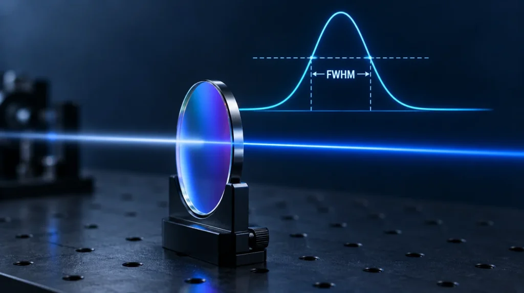
In an optical filter, FWHM (full width at half maximum) is the width of the passband, measured between the two wavelengths where transmission falls to half of the filter’s peak transmission. A bandpass filter with 90% peak transmission and a 10 nm FWHM stays above 45% transmission over a 10 nm-wide region. Its center wavelength (CWL) is normally defined as the midpoint between those two half-maximum points.
FWHM is the bandwidth figure most often quoted on bandpass, narrowband and laser-line filter datasheets. On its own, however, it says nothing about how flat the passband is, how steep the edges are, or how well the filter blocks light outside the band. This guide covers how FWHM is read from a transmission curve, what it leaves out, how operating and test conditions change it, and how to write it into a specification that can be verified.
What FWHM Means on a Filter Transmission Curve
FWHM is read from a spectral transmission curve (transmission versus wavelength) in four steps:
- Find the peak transmission, Tpeak, inside the passband.
- Calculate the half-maximum level, Tpeak / 2.
- Find the wavelengths where the curve crosses that level on the rising and falling edges: λ1 on the short-wavelength side and λ2 on the long-wavelength side. If passband ripple makes the curve cross the level more than twice, use the outermost crossings on the two transition slopes.
- Calculate FWHM and CWL from those two points.
CWL = (λ1 + λ2) / 2
Half of the Peak, Not 50% Absolute
“Half maximum” means half of the filter’s own peak transmission, not the 50% transmission line on the chart. The difference matters most when peak transmission is modest, as it can be for some UV filters or very narrow passbands. If a filter peaks at 60%, its FWHM is read at 30%. Reading it at 50% absolute gives a narrower and incorrect width, and for a filter whose peak is below 50% there would be no crossing at all. Some datasheets quote bandwidth at other levels or at an absolute transmission value, so confirm the definition before comparing filters from different sources.
CWL Versus Peak Wavelength
The CWL derived from the half-maximum points is not necessarily the wavelength of maximum transmission. When a passband is asymmetric or has ripple, the two can differ. If the source wavelength must sit at a specific position in the band, state which definition the specification uses.
FWHM Is Not the Same as the Usable Passband
At λ1 and λ2, the filter already transmits only half of its peak value. A laser line sitting near either edge of the FWHM loses about half its power. Because the transition slopes are steep there, a small wavelength shift also produces a large change in signal. The region where transmission stays close to the peak, for example at or above 90% of Tpeak, is always narrower than the FWHM. How much narrower depends on the passband shape: multi-cavity flat-top designs keep more of the FWHM near the peak than Gaussian-like profiles do (see flat-top vs Gaussian bandpass filters).
If the source must be transmitted at high efficiency, specify a minimum transmission over a defined wavelength range in addition to FWHM, in the form “T ≥ X% from λa to λb“. This states directly what the system needs, which FWHM alone does not.
What FWHM Does Not Tell You
Two filters can share the same CWL and FWHM and still perform very differently in a system. FWHM records only two points on the curve.
| Characteristic | What it describes | Why FWHM does not capture it |
|---|---|---|
| Passband flatness and ripple | How transmission varies inside the band | FWHM uses only the two half-maximum crossings |
| Edge steepness; width at 10%, 1% or 0.1% of peak (FW10%M, FW1%M, FW0.1%M) | How quickly transmission falls below half maximum | Filters with the same FWHM can have very different widths near the base of the passband (see edge steepness) |
| Out-of-band blocking (OD) | Rejection of wavelengths away from the passband | Blocking depends on the blocking design and range and needs its own specification (see OD blocking range) |
| Peak or average transmission | Signal throughput | FWHM is the same whether the passband top is at 95% or 60% |
| Integrated (equivalent) bandwidth | Total broadband light the filter passes | It depends on the full shape of the curve, not just its width at half maximum |
Same FWHM, Different Amount of Background Light
When the background has a broad, flat spectrum, the light that reaches the detector is proportional to the area under the transmission curve. For the same peak transmission and FWHM, that area is about:
- 1.00 × Tpeak × FWHM for an ideal rectangular passband
- 1.06 × Tpeak × FWHM for a Gaussian passband
- 1.57 × Tpeak × FWHM for an idealized Lorentzian passband
The Lorentzian figure matters because a single-cavity (Fabry–Pérot) interference filter has a transmission peak close to Lorentzian, with broad wings. Adding cavities makes the passband more rectangular and the slopes steeper. Ratios such as FW1%M/FWHM are therefore sometimes used as a shape factor to describe how close a passband is to rectangular. In a real filter, the blocking design limits the far wings, but the near-band difference remains.
Why FWHM Matters: Signal Versus Background
Choosing an FWHM is a trade-off between passing the source signal and rejecting everything else. The right value depends mainly on how wide the source spectrum is compared with the filter.
Narrow-Line Sources Such as Lasers
When the laser linewidth is much narrower than the FWHM and stays within the flat part of the passband, narrowing the filter barely changes the signal. Broadband background, by contrast, falls roughly in proportion to the passband width. If the detector is limited by background shot noise, signal-to-noise ratio improves roughly as 1/√FWHM.
The lower limit on FWHM comes from the tolerance stack: laser wavelength tolerance and temperature drift, filter CWL tolerance, and the passband shift caused by angle of incidence, beam convergence and filter temperature. Once these shifts can push the laser line onto a transition slope, a narrower filter costs more signal than it saves in background. Optical filter spectral tolerance covers this budget in detail.
Broadband Sources Such as LEDs and Fluorescence
When the source spectrum is itself broad, narrowing the FWHM below the source width removes signal as well as background. The table below uses a simple model:
- A Gaussian LED spectrum with a 40 nm FWHM
- A centered Gaussian filter with the same peak transmission in each case
- A flat background spectrum
- A detector limited by background shot noise
| Filter FWHM | LED power passed* | Relative background | Relative signal-to-background | Relative SNR (background-limited) |
|---|---|---|---|---|
| 10 nm | 24% | 1× | 1.00 | 0.69 |
| 20 nm | 45% | 2× | 0.92 | 0.89 |
| 40 nm | 71% | 4× | 0.73 | 1.00 |
| 80 nm | 89% | 8× | 0.46 | 0.89 |
*Relative to the filter’s peak transmission. Illustrative calculation under the stated assumptions; these are not measured filter data.
In this model, the narrowest filter gives the best signal-to-background ratio but the lowest SNR, and SNR peaks when the filter FWHM roughly matches the source FWHM. Other system conditions change the best choice:
- Detector read noise dominates: passing more signal matters more, which favors a wider filter.
- Ambient light saturates the sensor, or image contrast is the requirement: rejecting background matters more, which favors a narrower filter.
Either way, the choice comes from the source, the detector and the noise regime, not from a rule that narrower is better.
Conditions That Change the Effective FWHM
A datasheet FWHM is valid for the conditions under which it was measured, typically collimated light at a stated angle and room temperature. In service, the filter may not see those conditions.
Angle of Incidence and Polarization
Tilting an interference filter shifts its passband toward shorter wavelengths. At oblique incidence, s- and p-polarized light shift by different amounts, and for many dielectric designs the bandwidth changes in opposite directions for the two polarizations. With unpolarized light, the combined passband can appear wider, with a lower and less regular top. See how polarization affects filter spectra at oblique incidence.
Converging or Diverging Beams
In a converging or diverging beam, the filter sees a range of angles at once. The resulting average curve is shifted toward shorter wavelengths, broadened, and lower at the peak, and narrow filters are affected most. See cone half angle effects on interference filters.
Temperature
Temperature mainly moves the passband rather than reshaping it. For a narrow filter, that movement still uses up part of the margin between the source wavelength and the band edges. The operating temperature range therefore belongs in the specification.
Measurement Bandwidth and Beam Geometry
A spectrophotometer has a finite spectral bandwidth, which smears the recorded curve: the measured FWHM reads wider and the peak reads lower than the filter’s true response. For roughly Gaussian shapes, a useful estimate is:
Here SBW is the instrument’s spectral bandwidth. Some examples:
- A 1 nm filter measured with a 0.5 nm SBW reads about 1.12 nm, roughly 12% too wide.
- A 10 nm filter measured with a 2 nm SBW reads about 10.2 nm.
Test beam angle and convergence matter for the same reasons as in service. Measurement position on a large part can also matter where coating uniformity varies across the aperture. How to read an optical filter transmission curve covers these test conditions in more detail.
Converting FWHM to Relative Bandwidth and Wavenumber
The same FWHM in nanometres covers a different spectral range at different wavelengths. Relative bandwidth is FWHM divided by CWL. In spectroscopy, and especially Raman work where shifts are given in wavenumbers, the conversion below is useful when FWHM is much smaller than CWL:
A 10 nm FWHM corresponds to about 353 cm−1 at 532 nm, about 162 cm−1 at 785 nm, and about 88 cm−1 at 1064 nm. When a filter is moved to a different wavelength, keeping the same FWHM in nanometres does not keep the same spectral coverage.
How to Specify FWHM for a Bandpass Filter
An FWHM specification is useful only if both the supplier and the inspector read it the same way. A verifiable specification usually states:
- Nominal FWHM with a tolerance, for example 10 ± 2 nm (format example only; the actual values come from the system budget).
- The definition: width at half of peak transmission, and how CWL is derived.
- CWL with its tolerance, which works together with FWHM to decide whether the source stays in the band.
- Minimum peak or average transmission, and the wavelength range over which it applies.
- Near-band and out-of-band requirements: widths at lower transmission levels, edge requirements, or an OD blocking range, where rejection close to the band matters.
- Test conditions: AOI, cone half-angle, polarization, temperature and measurement resolution.
- System information: source spectrum and wavelength drift, detector spectral range, and how the filter is mounted in the beam.
Common Mistakes
- Reading FWHM at 50% absolute transmission instead of half of the peak.
- Placing the source wavelength near the edge of the FWHM instead of inside the flat part of the passband.
- Treating FWHM as a blocking specification.
- Specifying a very narrow FWHM at 0° for a filter that will be tilted or used in a converging beam.
- Comparing FWHM values from datasheets measured under different conditions or with different definitions.
FAQ
Is a narrower FWHM always better?
No. With a narrow-line laser, a narrower FWHM usually improves background rejection, but only until wavelength tolerances and drift push the laser line onto a transition slope. With LEDs, lamps or fluorescence emission, narrowing the FWHM below the source width also removes signal, and system SNR can fall. The right FWHM follows from the source spectrum, the tolerance budget and the detector’s noise regime.
Is FWHM the same as “bandwidth” or “half bandwidth” on a datasheet?
Often, but not always. Many filter datasheets use “bandwidth” or “half bandwidth” (HBW) to mean the full width at half of peak transmission. In general physics, HWHM (half width at half maximum) means half of the FWHM. Because both usages exist, confirm the definition before comparing parts or setting a tolerance.
Does FWHM change with angle of incidence?
Yes. For interference filters, increasing the AOI shifts the passband to shorter wavelengths and changes the bandwidth differently for s- and p-polarized light. In unpolarized or converging light, the effective passband typically broadens and its peak drops. If the filter will not be used at normal incidence in collimated light, specify FWHM at the actual operating AOI and beam geometry.
Why does a measured FWHM differ from the datasheet value?
Common causes are the spectrophotometer’s spectral bandwidth, a test beam that is not collimated, a different AOI or polarization, temperature, and the measurement position on the part. Small differences in how the half-maximum points are read, such as peak-relative versus absolute, also matter. Agreeing on the test method before ordering avoids most of these disputes.
What is the difference between FWHM and FW10%M or FW1%M?
FWHM is the passband width at 50% of peak transmission. FW10%M and FW1%M are the widths at 10% and 1% of peak. Comparing them with FWHM shows how quickly the passband edges fall. A filter whose FW1%M is close to its FWHM has a more rectangular passband and rejects near-band light better than a filter with the same FWHM and broader skirts.
Specifying FWHM for a Custom Filter Project
FWHM is most useful when it is set from the system’s needs: the source spectrum and its drift, the detector, the background to be rejected, and the angles and temperatures the filter will see. GIAI Photonics reviews custom optical filter projects against the optical specification, substrate, geometry, coating conditions and inspection criteria before defining the manufacturing route; see the custom optics process.
For a technical review, send your specification or drawing with the following:
- CWL and FWHM with tolerances
- Required transmission range
- Blocking range and OD
- AOI and cone angle
- Polarization and operating temperature
- Source and detector type
- Dimensions and expected quantity
References: H. A. Macleod, Thin-Film Optical Filters, 5th ed., CRC Press, 2018; ASTM E958, Standard Practice for Estimation of the Spectral Bandwidth of Ultraviolet-Visible Spectrophotometers.