
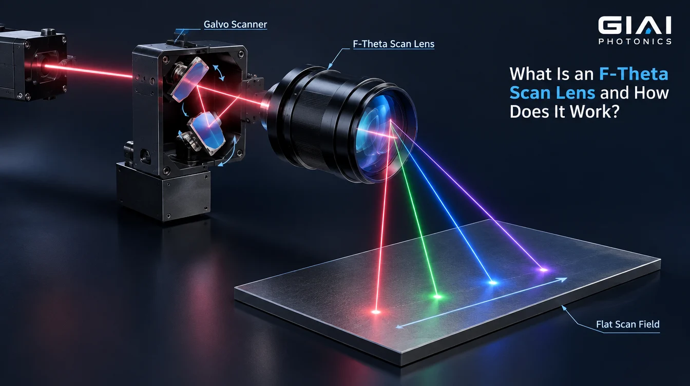
The topic is suitable as a foundational definition page. GIAI already has more specific content covering 1064 nm F-theta lenses, field-size calculation, standard vs. telecentric designs, and F-theta lens selection, so this page should act as the conceptual pillar rather than duplicate those narrower articles. The English content guide specifically prioritizes this engineering-first, search-intent-driven structure.
What Is an F-Theta Scan Lens and How Does It Work?
An F-theta scan lens is a specialized focusing lens used in laser scanning systems. It converts the angular movement of a laser beam—typically produced by galvanometer mirrors—into controlled movement of a focused spot across a substantially flat working plane.
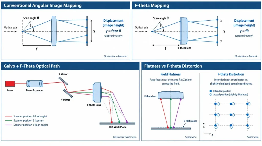
Its name comes from the approximate relationship:
where y is the focused spot position relative to the field center, f is the effective focal length of the scan lens, and θ is the optical scan angle in radians.
This approximately linear angle-to-position relationship is one of the key differences between an F-theta lens and a conventional focusing optic. F-theta lenses are widely used where a laser spot must move rapidly across a workpiece, including laser marking, engraving, drilling, welding, cutting, micromachining, and other scanning optical systems. The fundamental F-theta design principle—image height proportional to scan angle—is also documented in optical-design literature.
What Does an F-Theta Scan Lens Actually Do?
A typical laser scanner needs to perform two tasks simultaneously:
- move the laser spot to different X-Y positions; and
- keep the beam properly focused as it moves across the working area.
The galvanometer scanner performs the first task. The F-theta lens performs much of the second.
A simplified optical path is:
Laser source → beam conditioning → X galvo mirror → Y galvo mirror → F-theta scan lens → workpiece
The two galvanometer mirrors rotate through small angles. Their rotation changes the direction of the beam entering the scan lens. The lens then converts each input angle into a corresponding focused position on the work surface.
At the center of the field, the laser travels close to the optical axis. As the galvo mirrors rotate, the beam enters the F-theta lens at increasing off-axis angles and the focus moves across the processing field.
This is why an F-theta lens should not be treated simply as a normal lens with a particular focal length. It is part of a complete scanner–lens–workplane optical system.
Why Is It Called an “F-Theta” Lens?
The term describes its intended scan mapping.
For an idealized one-dimensional F-theta system:
where:
- y = image height or scan displacement
- f = effective focal length
- θ = optical scan angle in radians
If the scanner changes the beam angle by equal angular increments, the focused spot therefore moves by approximately equal linear increments across the work plane.
For example, increasing θ from 0.10 rad to 0.20 rad ideally doubles the displacement from the optical axis.
This relatively linear relationship is useful because the scanner controller can associate mirror angle with workpiece position more directly.
F-Theta Versus f × tan(θ)
A conventional geometric relationship commonly encountered in rectilinear imaging is:
At small angles, θ and tan θ are similar. As the angle becomes larger, however, the difference increases.
An F-theta lens is deliberately designed with controlled optical distortion so that its scan mapping approaches:
rather than simply following the tangent relationship.
In other words, distortion is not necessarily something that was accidentally left in the F-theta design. A controlled form of distortion is part of how the desired angle-to-position mapping is produced. Optical-design research describes F-theta objectives in the same terms: image height is made proportional to incident beam angle through intentional distortion control.
How Does an F-Theta Lens Create a Flat Scanning Field?
Creating the F-theta relationship is only part of the design problem.
The workpiece in a laser machine is normally flat. A scan lens therefore also needs to control field curvature and off-axis aberrations so that the focused beam remains near the intended work plane as the spot moves from the center toward the edge.
This is usually accomplished with a multi-element optical design rather than a single simple lens.
The optical designer has to balance several characteristics at the same time:
| Optical characteristic | Why it matters |
|---|---|
| F-theta distortion | Determines how closely spot position follows the intended fθ mapping |
| Field curvature | Determines how closely focus remains on the flat work plane |
| Spot size | Influences achievable processing feature size |
| Astigmatism and coma | Can change spot shape toward the field edge |
| Aperture | Must accommodate the moving beam without excessive clipping |
| Working distance | Determines physical spacing between lens and processing surface |
| Telecentricity | Controls how much the beam angle changes across the work plane |
| Coating | Must suit the operating wavelength and application conditions |
These parameters interact. Improving one characteristic may impose constraints elsewhere in the optical design.
Field Flatness and F-Theta Distortion Are Not the Same Thing
This distinction is important.
Field flatness describes whether the best focus remains close to a common plane as the beam moves across the field.
F-theta distortion describes how accurately the lateral spot position follows the intended relationship:
A scan lens can therefore have a relatively flat focal surface while still exhibiting measurable coordinate error.
Likewise, good F-theta mapping does not automatically guarantee identical spot quality everywhere in the field.
For precision equipment, engineers should evaluate these specifications separately rather than treating “flat field” as a complete description of scan-lens performance.
How a Galvanometer Scanner Works with the F-Theta Lens
Most two-dimensional laser scanning heads use two galvo mirrors.
One mirror controls one scanning axis and the second controls the other. As their angular positions change, the beam direction entering the F-theta lens changes.
There is an additional detail that matters when interpreting scan-angle specifications:
mirror mechanical angle and optical beam-deflection angle are not the same quantity.
For reflection from a rotating mirror, the reflected beam changes direction by approximately twice the mirror’s mechanical rotation angle.
A mechanical rotation of θm therefore produces approximately:
This is one reason engineers should confirm whether a scanner or lens specification is quoting mechanical mirror angle, optical scan angle, or total angular range before performing field calculations.
What Determines the Scan Field Size?
The simple F-theta equation gives useful first-order insight.
For a one-dimensional symmetric scan with maximum optical angle ±θmax:
where W is the ideal geometric scan width.
This equation explains why increasing focal length generally increases the potential scan width for a given scan angle.
But it does not mean that any field calculated with this equation is automatically usable.
Real field size may be limited by:
- scanner mirror aperture
- input beam diameter
- distance between the two galvo mirrors
- scanner-to-lens spacing
- lens clear aperture
- vignetting
- allowable spot degradation
- residual distortion
- telecentricity requirements
- mechanical packaging
GIAI’s existing technical resource on F-theta field calculation discusses this distinction in more detail.
Why Input Beam Diameter Matters
Beam diameter is closely connected to focused spot size and aperture requirements.
For a near-Gaussian beam, the diffraction-related focal spot generally becomes smaller when:
- wavelength becomes shorter,
- focal length becomes shorter, or
- the usable collimated beam diameter becomes larger.
The exact result also depends on beam quality, usually characterized in laser systems by M², as well as lens aberrations and system geometry.
This creates an important engineering trade-off.
A larger beam can help reduce the theoretical focused spot, but it also occupies more of the galvo mirror and scan-lens aperture. At large scan angles, insufficient aperture may cause clipping or vignetting.
Therefore:
larger input beam diameter is not automatically better.
Beam diameter, scanner aperture, scan angle, focal length and required field should be evaluated together.
Is Working Distance the Same as Focal Length?
No.
Effective focal length (EFL) is an optical property used in the F-theta mapping and optical design.
Working distance generally refers to a physical distance between a defined mechanical or optical reference on the scan lens and the working plane.
Because an F-theta lens normally contains several optical elements inside a housing, its principal planes do not necessarily coincide with the front or rear mechanical surfaces.
Therefore, a lens with a particular EFL does not necessarily have the same numerical working distance.
This difference matters when replacing a lens or integrating one into an existing machine.
Standard F-Theta vs. Telecentric F-Theta Lenses
Not every F-theta lens is telecentric.
With a standard F-theta lens, the beam can become progressively more oblique to the workpiece as the focused spot moves toward the edge of the field.
A telecentric F-theta lens adds another optical requirement: the focused beam axis should remain closer to perpendicular to the work surface across the specified field.
Telecentricity can matter when incidence angle affects processing geometry, particularly in applications involving holes, structured surfaces, dimensional measurement, or other angle-sensitive processes.
However, telecentricity should not be confused with overall lens accuracy.
A telecentric design does not automatically guarantee:
- lower F-theta distortion,
- a smaller focused spot,
- better field flatness, or
- higher coordinate accuracy.
These are separate optical characteristics. GIAI has a dedicated comparison discussing this distinction in more detail.
Why Does an F-Theta Lens Still Need Calibration?
The ideal equation:
describes the intended first-order mapping. A real scanner system is more complicated.
Residual coordinate errors can come from:
- F-theta lens distortion
- separation between X and Y galvo mirrors
- scanner angular response
- lens mounting position
- mechanical alignment
- controller scaling
- assembly tolerances
- working-plane position
- thermal drift
In an XY scanner, the two mirrors are physically separated, so they do not rotate the beam about exactly the same optical pivot. This becomes increasingly relevant as field size and scan angle increase.
For this reason, high-accuracy laser systems normally treat optical design and machine calibration as complementary steps.
A nominally low-distortion scan lens does not eliminate the need to calibrate the installed scanner, lens, controller and mechanical system together.
What Specifications Matter When Selecting an F-Theta Scan Lens?
Choosing a scan lens from wavelength alone is insufficient.
A practical specification should consider:
| Parameter | Engineering significance |
|---|---|
| Laser wavelength | Determines optical design and coating requirements |
| Laser operating mode | CW, nanosecond, picosecond and femtosecond systems may impose different requirements |
| Input beam diameter | Affects spot size and required aperture |
| Beam quality / M² | Influences achievable focused spot |
| Galvo aperture | Limits usable beam diameter |
| Mirror spacing | Affects beam walk and scan geometry |
| Effective focal length | Influences field size and focusing geometry |
| Required scan field | Defines usable processing area |
| Working distance | Affects machine integration |
| Optical scan angle | Influences field size and off-axis performance |
| F-theta distortion | Influences positional mapping |
| Telecentricity | Matters where incidence angle is important |
| Mechanical interface | Housing, mounting thread and references must fit the equipment |
| Application conditions | Power, pulse regime and environment can affect component requirements |
There is no single F-theta lens specification that is optimal for every laser scanner.
Common F-Theta Lens Specification Mistakes
Several errors occur repeatedly when a scan lens is selected as an isolated component rather than as part of the optical system.
Matching only the wavelength.
A wavelength such as 355 nm, 532 nm or 1064 nm identifies only one part of the requirement. Scanner geometry, beam diameter, field size, focal length, coating conditions and laser operating conditions still matter.
Using EFL as the working distance.
These values describe different quantities and should be taken from the applicable optical and mechanical specifications.
Calculating field size only from fθ.
The calculation is useful for first-order geometry, but aperture, vignetting and edge performance determine the practical usable field.
Assuming the spot is identical everywhere.
Residual aberrations and beam geometry can make spot size and spot shape field-dependent.
Assuming every F-theta lens is telecentric.
Telecentricity is an additional design requirement, not an inherent consequence of F-theta mapping.
Ignoring the galvo geometry.
Mirror aperture, mirror separation and scanner-to-lens distance can materially affect system performance.
What Should Be Specified for a Custom F-Theta Lens Project?
For an OEM or replacement scan-lens project, useful technical inputs include:
- laser wavelength or wavelength range
- CW or pulsed operation
- pulse duration, pulse energy and average power where relevant
- input beam diameter
- beam quality M², if available
- galvo mirror aperture
- distance between scanner mirrors
- scanner-to-lens geometry
- required scan field
- desired EFL or existing lens specification
- required working distance
- optical scan-angle range
- target spot or process feature requirement
- allowable F-theta distortion
- telecentricity requirement, if applicable
- housing dimensions and mounting thread
- coating requirements
- drawing, sample or existing lens information
- required inspection criteria
- prototype and production quantity
GIAI lists laser components within its current English optical-component structure, while its controlled company references support project-level evaluation of optical components from drawings, specifications and samples. GIAI’s manufacturing workflow includes optical grinding, polishing, coating and inspection, with the specific route determined by the actual project requirements.
For a custom project, the useful starting point is therefore not simply:
“I need an F-theta lens.”
A more complete request is:
“This is the laser wavelength, beam diameter, scanner geometry, required field, working distance and acceptance criteria.”
That allows the scan lens to be evaluated in the context of the system in which it will actually operate.
FAQ
What does F-theta mean in an F-theta lens?
“F-theta” refers to the intended relationship between the effective focal length f, optical scan angle θ, and focused spot position. In an idealized one-dimensional system, the position follows approximately y = fθ. The relationship allows approximately linear spot displacement for linear changes in optical scan angle.
What is the difference between an F-theta lens and a normal focusing lens?
A conventional focusing lens is generally optimized to form a focus around a particular optical geometry. An F-theta lens is specifically designed for an angularly scanned beam. It must control off-axis aberrations and field curvature while providing approximately linear angle-to-position mapping across a defined scan field.
Does an F-theta lens keep exactly the same spot size across the entire field?
Not necessarily. The design attempts to maintain useful focusing performance across the specified field, but practical spot size and shape depend on diffraction, beam diameter, M², lens aberrations, scan position, wavelength and system geometry. “F-theta” describes the intended scan mapping; it does not by itself guarantee perfectly constant spot size.
Does a longer focal length give a larger scanning area?
For the same optical scan angle, a longer focal length increases the first-order displacement predicted by y = fθ. In practice, usable scan area also depends on lens aperture, beam diameter, galvo geometry, vignetting, aberrations and acceptable edge performance.
Is every F-theta lens a telecentric lens?
No. Standard F-theta lenses can provide flat-field scanning and controlled fθ mapping while the beam becomes increasingly oblique toward the field edge. Telecentric F-theta lenses add a separate requirement to keep the chief-ray angle closer to the work-plane normal.
Where is the F-theta lens installed in a laser system?
In a common post-objective galvo scanning system, it is installed after the X-Y scanning mirrors:
laser → beam conditioning → galvo mirrors → F-theta lens → workpiece.
The scanner determines beam angle and the F-theta lens focuses the deflected beam onto the corresponding location on the working plane.