
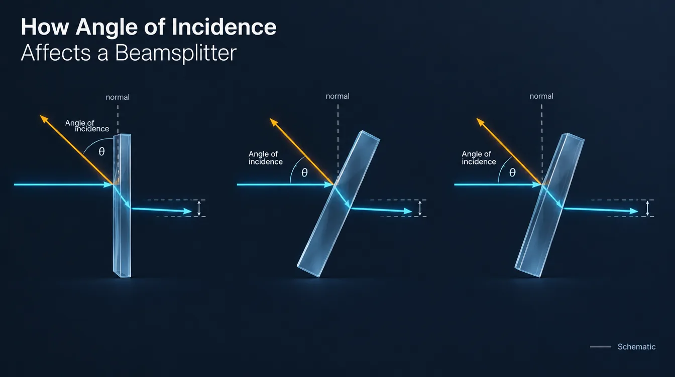
Angle of incidence affects a beamsplitter by changing its reflection and transmission, its response to s- and p-polarized light, and the direction of the output beams. For dichroic coatings, it can also shift the wavelength transition between reflection and transmission. A specified splitting ratio therefore applies to a defined wavelength range, polarization condition and incidence angle—not every possible mounting position.
A beamsplitter may produce the expected balance on an optical bench, then deliver unequal detector signals after installation. Before attributing the difference to coating quality, check the operating angle, polarization and collection geometry. These can change together when the optic is adjusted.
Which angle matters: the surface or the coating?
Angle of incidence (AOI) is measured between the incoming ray and the surface normal. The normal is perpendicular to the surface. Normal incidence is 0°; a ray travelling nearly parallel to the surface has an AOI approaching 90°.
For a plate beamsplitter with its splitting coating facing air, the external beam angle usually describes the coating AOI directly. Many plates are designed for 45° operation, but other design angles are possible.
A conventional cube has a different geometry: a beam entering perpendicular to the outer face has 0° external AOI, yet encounters the diagonal internal coating at approximately 45°. Tilting the cube changes the internal angle through refraction. Specify the reference surface and incident medium rather than writing “45°” without a drawing. [1]
Why angle of incidence changes the splitting ratio
Two effects matter. Reflection at each material boundary depends on incidence angle and polarization. In a multilayer dielectric coating, angle also changes the phase relationship between waves reflected at different layer boundaries. The combined coating response consequently depends on wavelength, angle and polarization.
The polarization directions are defined relative to the plane containing the incident ray and the surface normal:
- s-polarization: the electric field is perpendicular to this plane.
- p-polarization: the electric field lies within this plane.
At oblique incidence, the two components generally have different reflection and transmission responses. A coating can reduce this difference over a specified operating range. Increasing AOI does not universally increase or decrease the reflected power of a coated beamsplitter; the direction and magnitude depend on the actual design. [2]
Read “50:50” together with its conditions
A 50:50 label alone is incomplete. Check whether it describes s-polarization, p-polarization, unpolarized light, or a non-polarizing specification covering both components. A ratio measured with unpolarized light may conceal different responses for the two polarizations.
For unpolarized incident light, when total optical power is collected without polarization-selective detection:
Runpol = (Rs + Rp) / 2
Tunpol = (Ts + Tp) / 2
Here, R and T are power reflectance and transmittance, referenced to incident power. The average assumes equal incident power in the two polarization components. [2] Equal reflected and transmitted outputs do not necessarily mean each receives half the incident power: absorption and other losses can reduce their sum. Check absolute R and T as well as the output ratio. [3]
Different beamsplitters respond differently
| Beamsplitter type | What to evaluate when AOI changes |
|---|---|
| Dielectric intensity splitter | R/T balance at the operating wavelength and the separate s/p responses. |
| Non-polarizing beamsplitter | Whether R/T tolerances and the allowed s/p difference remain satisfied. |
| Polarizing beamsplitter | Desired-polarization throughput and unwanted-polarization leakage at each required port. |
| Dichroic beamsplitter | Transition wavelength, reflection/transmission bands and polarization-dependent edge separation. |
| Metallic or hybrid splitter | Angular response together with absorption and total throughput; the coating is not automatically angle-independent. |
“Non-polarizing” describes a limited difference in power splitting for the two polarization components under specified conditions. It does not imply unlimited angular acceptance, nor does it guarantee preservation of every input polarization state. Different s/p phase shifts can matter even when their output powers are closely matched. [3]
For dichroic beamsplitters, watch the spectral edge
A dichroic beamsplitter routes different wavelength bands to different outputs. For many dielectric interference designs, increasing AOI moves spectral features toward shorter wavelengths, commonly called a blue shift. The s- and p-polarized edges can also shift by different amounts. [4]
If a laser line sits close to the transition region, an angular adjustment may transfer more of that line into the other port. In a fluorescence system, the same mechanism can change excitation rejection or the fraction of emission reaching the detector.
Evaluate the required reflection and transmission bands across the complete operating angle range. Do not apply one universal “nanometres per degree” value to different coatings, or use a simple filter blue-shift estimate to predict a broadband intensity splitter’s R/T ratio.
A beam cone has more than one incidence angle
A nominal AOI describes a reference ray, often the chief ray. A converging or diverging beam contains a distribution of ray angles. A wide-field imaging system may also present different chief-ray angles at different field positions.
The detected response is therefore an average weighted by the light reaching the detector across angle, wavelength and polarization. Near a dichroic edge, this averaging can broaden the apparent transition or change channel balance. A collimated-beam curve at the nominal angle does not fully characterize this situation. [5]
Provide the beam cone half-angle or numerical aperture, its reference medium, and any field-angle range. Consider locating an angle-sensitive component in a more nearly collimated section when the optical layout permits.
Separate coating changes from beam movement
AOI adjustment also changes where light travels. For a fixed incident beam, rotating a planar reflecting surface by a small angle within the plane of incidence changes the reflected beam direction by twice that angle. This follows from the law of reflection. A detector can consequently record less power because the beam moves off its active area.
A plane-parallel plate at oblique incidence, in the same medium on both sides, produces a lateral displacement of the transmitted beam. That displacement varies with angle, substrate thickness and refractive index. [1] A wedged plate can also change the transmitted direction. Residual rear-surface reflections may produce additional spots or interference. [6]
Beam footprint also grows along the tilt direction. For a circular collimated beam of diameter D incident on a flat plate, the geometrical footprint length is D/cos θ. At 45°, this is approximately 1.41D. This is a geometry estimate, not a clear-aperture specification; a Gaussian beam also requires a stated diameter convention and clipping allowance.
How to verify performance at the working AOI
The following checks help distinguish the component’s optical response from changes introduced by the measurement setup:
- Define the optical conditions. Record wavelength or spectrum, coating-side orientation, incident medium, polarization, nominal AOI and beam divergence.
- Measure incident power. Use calibrated detection and monitor source drift. Calculate R = Preflected/Pincident and T = Ptransmitted/Pincident after accounting for the measurement paths.
- Collect the displaced beams. Check detector position, aperture clipping, detector angular response and any polarization-sensitive optics after every adjustment.
- Test the operating envelope. Include nominal angle and the required angular limits. Resolve s/p performance where needed; for a dichroic, evaluate the required bands rather than only one convenient wavelength.
- Check the assembled system. Repeat with the intended cone, field positions and downstream optics if these affect the application.
Agree whether acceptance concerns the splitting coating or the complete optic, including entrance/exit surfaces and substrate losses. For a polarizing splitter, define which output port requires an extinction ratio and how that ratio is measured. These choices belong in the inspection specification.
What to specify for an angle-sensitive beamsplitter
| Specification input | Information to provide |
|---|---|
| Optical function | Intensity splitting, polarization separation or wavelength separation; identify the ports used. |
| Spectral targets | Operating wavelengths or bands, required R/T, tolerances and whether targets are pointwise or band-averaged. |
| AOI and geometry | Nominal angle, allowed range, reference surface, incident medium, orientation and layout drawing. |
| Angular distribution | Collimated beam, cone half-angle or NA, and field-angle range where relevant. |
| Polarization | Input state, permitted s/p imbalance, required port extinction and phase requirements where relevant. |
| Mechanical requirements | Plate/cube format, substrate, dimensions, clear aperture, thickness or wedge, mounting and wavefront requirements. |
| Verification | Test conditions, acceptance criteria, report requirements, operating environment and expected quantity. |
Preparing a project for GIAI review
GIAI Photonics supports beamsplitters and related custom optical components. Projects are reviewed against the drawing, optical requirements, substrate, geometry, coating conditions and inspection criteria before the manufacturing route is defined.
Send the intended AOI range together with the wavelength bands, polarization state, beam geometry and R/T acceptance limits through the project inquiry page. Define the required verification and acceptance conditions during technical review. Related guidance is available in Filters & Coatings.
Frequently asked questions
Can I use a 45° beamsplitter at 30°?
Light will still reach the component, but the specified performance may not apply. Check R/T, polarization response, spectral bands and output geometry at 30°. Ask for angle-specific design or measurement data rather than assuming the published curve can be reused.
How much angular tolerance does a beamsplitter have?
There is no universal tolerance. The usable range ends where an application requirement fails—for example, R/T balance, dichroic rejection, polarization leakage or beam collection. Mechanical mounting tolerance and the angle range over which optical specifications are met should be defined separately.
Does rotating a cube beamsplitter avoid AOI sensitivity?
No. Rotation changes the refracted ray direction inside the cube and therefore the conditions at its splitting coating. Refraction means the internal change generally differs from the external rotation. The complete prism geometry must be considered when evaluating the coating and output beams.
Can I adjust the split ratio by tilting the optic?
Tilting may change the ratio, but also moves the output beam and can alter spectral and polarization performance. For deliberate variable splitting of a linearly polarized beam, a half-wave plate with a suitable polarizing beamsplitter is a common alternative. Check its wavelength range and both output-port requirements. [3]
Technical references
- Edmund Optics. What Are Beamsplitters?
- Semrock / IDEX Health & Science. Understanding Polarization.
- RP Photonics Encyclopedia, Dr. Rüdiger Paschotta. Beam Splitters.
- Semrock / IDEX Health & Science. Filter Spectra at Non-normal Angles of Incidence.
- Edmund Optics. The Importance of Optical Filter Orientation, Angle of Incidence, and Cone Half Angle.
- Evident, Matthew J. Parry-Hill and Michael W. Davidson. Transmission and Reflection by Beamsplitters.