
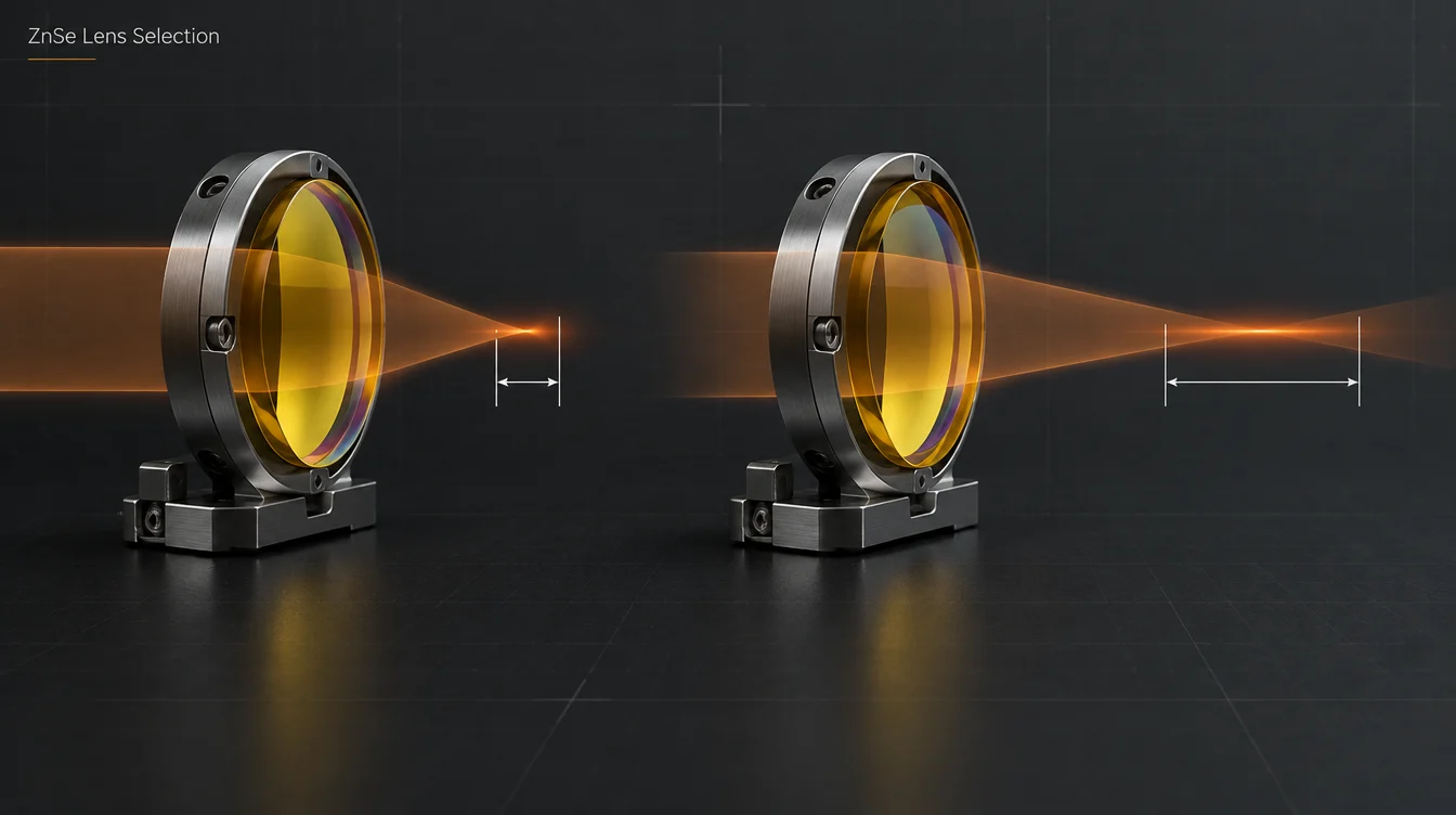
To choose a ZnSe lens, work from the system outward. First confirm the exact wavelength band and laser power, and check that zinc selenide is the right material. Then choose the material grade, calculate the focal length from the spot size and depth of focus you need, and pick the lens form. Size the clear aperture to the beam and specify an AR coating for the real wavelength and angle of incidence. Finally, decide how each of these parameters will be verified.
Most ZnSe lens problems in service trace back to a parameter that was chosen in isolation. Typical symptoms are focus drift, a wide kerf, low thermal-image contrast, or a replacement lens that does not sit at the right height in the holder. The steps below follow the order in which the decisions constrain each other.
The ZnSe lens selection sequence at a glance
| Step | Decision | Driven by | What ends up on the specification |
|---|---|---|---|
| 1 | Wavelength and lens role | Laser line or detector band; focusing, collimating or imaging | Design wavelength(s), conjugates |
| 2 | Material check | Band, visible alignment, power, environment | ZnSe or an alternative IR material |
| 3 | Material grade | Average power and absorption budget | Grade and, if needed, absorption requirement |
| 4 | Focal length | Spot size, depth of focus, head geometry | EFL at design wavelength, reference distance, tolerance |
| 5 | Lens form | f-number, beam size, cost | Plano-convex, meniscus or aspheric; radii |
| 6 | Diameter, clear aperture, thickness | Beam diameter, mount, gas pressure | Ø, CA, CT, ET and tolerances |
| 7 | Coating and verification | Operating band, AOI, power | Reflection per surface at λ and AOI; test methods |
Step 1: Define the wavelength band and what the lens has to do
Bulk CVD zinc selenide transmits from roughly 0.6 µm to about 21 µm. The usable range of a finished lens is narrower and depends on thickness and coating. That breadth is why the same material appears in CO2 laser heads, long-wave infrared (LWIR) imagers and FTIR accessories. The lens design and coating for each use are different, however.
- CO2 laser processing. Most systems run at 10.6 µm, but 9.3 µm and 10.2 µm sources are also used. Focal length and AR coating are specified at the laser line, and a lens optimized for one line is not automatically correct for another.
- LWIR imaging (8–12 µm or 8–14 µm). The lens must perform across a band. Broadband AR, chromatic behavior and thermal defocus matter more than single-line absorption.
- MWIR optics and spectroscopy. ZnSe is used in 3–5 µm systems and in FTIR sampling optics, where broadband transmission and careful handling are the main concerns.
- Visible alignment. ZnSe transmits red light, so a red diode can be co-aligned through the optic. Green 532 nm light falls below its useful transmission edge.
Also state the lens role. Focusing a collimated beam, collimating a diverging source and imaging at finite conjugates each lead to a different best-form shape, even at the same focal length.
Step 2: Confirm that ZnSe is the right material
ZnSe combines several useful properties:
- Very low absorption at 10.6 µm: about 0.0005 cm−1 in published data for CVD material.
- A moderate refractive index (n ≈ 2.40 at 10.6 µm).
- A comparatively low thermo-optic coefficient (dn/dT ≈ +61×10−6/K at 10.6 µm).
- Red-light transmission.
Its weaknesses are just as specific. It is soft (Knoop hardness around 120), it oxidizes at elevated temperature in air, and it costs more than silicon.
| If the priority is… | Usually consider | Reason |
|---|---|---|
| High-power CO2 focusing with visible alignment | ZnSe | Low absorption at 10.6 µm; transmits red alignment light |
| Compact LWIR imaging lens with few elements | Germanium, often combined with ZnSe or ZnS elements | n ≈ 4.0 means gentler curvatures, but dn/dT ≈ 396×10−6/K requires athermal design |
| Exposed outer optic (sand, rain, wiping) | Multispectral ZnS or hard-coated Ge | Uncoated ZnSe scratches easily |
| Low-cost, lightweight 3–5 µm optics | Silicon | Good MWIR transmission and low density; unsuitable across 8–12 µm because of strong lattice absorption near 9 µm |
For a fuller material comparison, see ZnSe vs germanium for infrared lenses and ZnSe vs ZnS infrared optics.
Step 3: Select the material grade for the power level
Laser-grade CVD ZnSe is selected for low bulk absorption and scatter at 10.6 µm. Standard (optical) grade is often adequate for imaging, spectroscopy and low-power beams.
Grade cannot be read from a transmission scan. A spectrophotometer measures transmission and reflection, but at the level that matters for kilowatt beams it cannot separate a small absorption from scatter. Laser calorimetry, standardized in ISO 11551, measures absorptance directly.
An order-of-magnitude check shows why the whole lens matters, not only the bulk. Bulk absorbed power is roughly α · t · P. For α = 0.0005 cm−1, a 5 mm thick lens and a 2 kW beam, that gives about 0.5 W. AR coatings and surface contamination can add more absorbed power than the substrate does, so a laser-grade blank still needs a low-absorption coating and a clean surface. Grade definitions, polishing versus diamond turning, and drawing tolerance tiers are covered in ZnSe lens manufacturer: grades, tolerances and coatings.
Step 4: Work out the focal length from spot size and depth of focus
Focal length should come from a calculation, not from habit. For a collimated beam focused by an aberration-free lens, the standard Gaussian-beam estimates are:
zR = π · w0² / (M² · λ), with w0 = d0 / 2
DOF ≈ 2 · zR (spot diameter grows by √2 at each end)
Here d0 is the focused 1/e² spot diameter, λ the wavelength, f the effective focal length, D the 1/e² beam diameter at the lens (not the lens diameter), and M² the beam quality factor defined in ISO 11146. Two relations drive most decisions: spot size scales with f, and depth of focus scales with f². Halving the focal length halves the spot but leaves only about a quarter of the depth of focus.
| EFL | Working f-number (f/D) | Ideal spot d0 | Ideal DOF (2zR) |
|---|---|---|---|
| 38.1 mm (1.5 in) | ≈ f/3.8 | ≈ 62 µm | ≈ 0.47 mm |
| 63.5 mm (2.5 in) | ≈ f/6.4 | ≈ 103 µm | ≈ 1.3 mm |
| 127 mm (5 in) | ≈ f/12.7 | ≈ 206 µm | ≈ 5.2 mm |
Illustrative calculation: λ = 10.6 µm, M² = 1.2, D = 10 mm, diffraction-limited lens. These values are lower bounds, not measured GIAI data. At low f-numbers a plano-convex lens adds spherical aberration that enlarges the real spot (see Step 5).
The beam diameter at the lens is part of the same equation. Changing a beam expander has the same effect on the focus as changing the focal length: a larger D gives a smaller spot and a shorter depth of focus. Thick-section cutting usually benefits from a longer depth of focus, while fine engraving and marking favor a smaller spot. Use the calculation to narrow the candidates, then confirm the process window with test cuts.
EFL, back focal length and working distance
Effective focal length is measured from the lens’s principal plane. Cutting heads, however, are set up around a physical distance: lens surface to focus, or lens seat to nozzle tip. A meniscus lens and a plano-convex lens with the same EFL place their principal planes differently, so their focus sits at a different height in the same holder. State which distance the system references, and give a tolerance on it.
Focal length is wavelength-specific
Published index data give n ≈ 2.40 at 10.6 µm and n ≈ 2.59 near 0.63 µm. In the thin-lens approximation f is proportional to 1/(n − 1). A lens with f = 63.5 mm at 10.6 µm therefore focuses red light at roughly 56 mm, about 12 % shorter. Measuring focal length with a visible laser, without correcting for dispersion, can make a good lens look out of specification. Always quote focal length at the design wavelength, and set process focus with the infrared beam itself.
Step 5: Choose the lens form
| Form | Where it fits | Trade-off |
|---|---|---|
| Plano-convex | Longer focal lengths and higher f-numbers; general engraving; cost-sensitive replacements | Spherical aberration rises steeply as f-number falls; install with the convex side toward the collimated beam |
| Positive meniscus | Short focal lengths and larger beams in cutting and welding heads | Higher cost; orientation, edge thickness and seat geometry must match the holder |
| Aspheric or diffractive (often diamond-turned) | Imaging lenses, compact designs, near-diffraction-limited focusing at low f-numbers | Turning marks raise scatter; check suitability before using at high laser power |
Third-order spherical aberration blur grows roughly with the cube of 1/(f-number). Going from f/8 to f/4 therefore increases it about eightfold. That is why short-focal-length CO2 heads favor meniscus lenses, while long-focal-length heads often run well with plano-convex optics.
Step 6: Size the diameter, clear aperture and thickness
The clear aperture (CA) has to pass the beam with margin for pointing and alignment errors. For a Gaussian beam of 1/e² radius w passing a circular aperture of radius a, the transmitted fraction is:
| CA ÷ 1/e² beam diameter | Power passed (ideal Gaussian) |
|---|---|
| 1.25× | ≈ 95.6 % |
| 1.5× | ≈ 98.9 % |
| 2× | ≈ 99.97 % |
Clipped energy heats the lens edge and the mount, and adds diffraction rings around the focal spot. A ratio of about 1.5–2× is a common starting point. Use more margin for high-power beams, for beams that wander, or for non-Gaussian multimode profiles.
The clear aperture is smaller than the physical diameter because of the retaining ring, chamfers and the coating edge. Specify CA explicitly; clear aperture vs optic diameter explains the distinction.
Thickness is set mainly by the mechanics. Center thickness (CT) and edge thickness (ET) must suit the holder depth and retention method. In gas-assisted cutting heads, the lens must also withstand the pressure difference across it. A thinner lens absorbs slightly less in the bulk but is less stiff.
For a replacement lens, diameter, CT/ET, form and EFL must all match the head. Matching only the nominal focal length is not enough.
Step 7: Specify the AR coating for the real wavelength and angle
Uncoated ZnSe reflects about ((n − 1)/(n + 1))² ≈ 17 % per surface at 10.6 µm. Including multiple reflections, the two-surface loss is roughly 29 %. An AR coating is therefore a functional requirement, and the coating type follows from Step 1.
- Single-line AR at 10.6 µm, 10.2 µm or 9.3 µm gives the lowest reflection at that line. Reflection rises away from the design wavelength.
- Dual-wavelength AR covers the laser line plus a red alignment wavelength, when the alignment beam has to pass the lens efficiently.
- Broadband AR (for example 8–12 µm, 8–14 µm or 3–5 µm) suits imaging and spectroscopy. Average reflection across the band is low, but at any single wavelength it is normally higher than a single-line design.
Write the requirement as reflection per surface (maximum or band average) at a stated wavelength range and AOI, and state the polarization if the lens is tilted. For high-power systems, coating absorption and laser damage threshold matter as much as reflectance. Damage thresholds are meaningful only with their test wavelength, pulse duration and beam size; see what determines the laser damage threshold of a coating.
Thermal, mechanical and handling limits
- Thermal lensing. Absorbed power creates a radial temperature gradient. Through dn/dT and thermal expansion this shortens the effective focal length under load, and contamination makes it worse. A laser-grade blank, a clean surface and a holder with a good heat path, which is water-cooled at higher powers, keep focus drift under control. Drift that increases over time is an early sign of contamination or coating wear.
- Temperature. Published material data note significant oxidation around 300 °C and advise against use above about 250 °C in normal atmosphere.
- Softness. With a Knoop hardness near 120, ZnSe scratches easily. Use cleaning methods intended for ZnSe optics, and never dry-wipe the surface.
- Safety. ZnSe dust and decomposition products are toxic. Handle and dispose of cracked or burned lenses according to the supplier’s safety data sheet.
How to verify a ZnSe lens
| Parameter | Typical verification | Condition to state on the specification |
|---|---|---|
| Transmission / reflection | FTIR spectrophotometer scan | Wavelength range, AOI, per-surface or total, sample or witness piece |
| Absorption (high power) | Laser calorimetry (ISO 11551) | Test wavelength, coated lens or substrate |
| Focal length | Measured at, or converted to, the design wavelength | Design λ; EFL or back focal length |
| Surface figure | Interferometry, commonly at 632.8 nm | Test wavelength and test aperture |
| Surface imperfections | Visual scratch-dig (MIL-PRF-13830B) or ISO 10110-7 | Standard used and inspection conditions |
| Centration | Beam deviation or edge-runout measurement | Unit (arc min or µm) and reference axis |
Agree on these methods before the order is placed. A lens that passes one test method may fail another, and acceptance should be defined by the method that reflects the real operating condition.
Selection mistakes that are easy to miss
- Choosing focal length by habit. Copying the focal length from a previous machine ignores changes in beam diameter, M² or material thickness.
- Checking focal length with a visible laser. Dispersion shifts the red focus about 12 % shorter, so a correct lens can appear to be wrong.
- Swapping a meniscus for a plano-convex lens of the same nominal EFL. At short focal lengths, the spot grows and the focus height changes.
- Mixing up coating types. A 10.6 µm single-line AR lens is not a substitute for a broadband 8–14 µm imaging lens, and the reverse is also true.
- Planning a green alignment beam. ZnSe does not usefully transmit 532 nm light, so use a red source instead.
- Treating the mount as passive. At high power, the holder’s heat path is part of the optical performance.
What to send with a ZnSe lens RFQ
- Operating wavelength(s) and bandwidth, including any alignment wavelength.
- Laser power (CW or average; peak power and pulse duration if pulsed), M² and the 1/e² beam diameter at the lens.
- Required spot size and depth of focus, or the EFL with the reference distance and its tolerance.
- Lens form, diameter, clear aperture, center and edge thickness, or a drawing or sample of the existing lens and holder.
- Material grade, and an absorption requirement for high-power use.
- Coating: reflection per surface at the stated wavelength and AOI, plus any damage-threshold test requirement.
- Surface figure, the scratch-dig standard, centration and the inspection methods.
- Quantity and the operating environment.
FAQ
Does a shorter focal length ZnSe lens always cut better?
No. A shorter focal length gives a smaller spot and higher intensity, which helps on thin material and fine features. It also shrinks the depth of focus with the square of the focal length, makes focus height more critical, and shortens the distance between lens and workpiece, which raises the risk of spatter. Thicker sections usually need the longer depth of focus of a longer focal length lens.
Can I align a ZnSe lens system with a visible laser?
Yes, with a red source. ZnSe transmits red light but not green 532 nm. The visible beam comes to focus at a different position than the 10.6 µm beam because of dispersion. Use it to check beam centering, then set the working focus with the infrared beam, for example with a ramp or spot test.
Is ZnSe a good choice for 1 µm fiber lasers?
ZnSe does transmit at 1 µm, but published data show its absorption near 1.3 µm is about ten times higher than at 10.6 µm. High-power near-infrared optics normally use fused silica, which is better matched to that band. ZnSe is chosen mainly for mid- and long-wave infrared applications, and when a visible-to-LWIR path through one material is needed.
How do I know when a ZnSe lens needs replacing?
Watch for a focus position that drifts during operation, the need for more power to achieve the same cut, visible discoloration, coating damage, pits or burn marks inside the clear aperture. Cleaning can remove surface contamination, but it cannot restore a damaged coating or a substrate that has absorbed enough energy to change.
Which focal length is a sensible starting point for a CO2 engraver?
In common practice, roughly 1.5–2 inch lenses are used for fine engraving on thin materials, and roughly 2.5–4 inch lenses for thicker materials and deeper cuts. Treat these ranges as a starting point. The actual choice depends on beam diameter, beam quality and material, and should be confirmed with the spot and depth-of-focus calculation above and with test runs.
Working with GIAI on ZnSe lenses
ZnSe is one of the infrared materials GIAI Photonics processes. The current ZnSe lens product page lists plano-convex and meniscus focusing lenses for 10.6 µm, with 10.6 µm AR or 8–14 µm broadband AR options. Non-standard geometries, wavelengths and coatings are reviewed project by project against the drawing, sample, optical requirements, material, geometry, coating requirements and inspection criteria before the manufacturing route is defined; the steps are outlined on the custom optics process page.
Specifying a ZnSe lens? Send the wavelength, laser power and beam diameter, the required spot size or EFL, the lens and holder dimensions or a drawing, and your coating and inspection requirements. Contact Susan Deng at susan@giaitech.com or through the contact page for a technical review.
References
- Crystran, Zinc Selenide (ZnSe) material data: transmission range, refractive index, dn/dT, absorption, thermal and mechanical properties.
- Edmund Optics, infrared material property table: refractive index and dn/dT of germanium and ZnSe.
- ISO 11146-1, Lasers and laser-related equipment — Test methods for laser beam widths, divergence angles and beam propagation ratios.
- ISO 11551, Optics and optical instruments — Lasers and laser-related equipment — Test method for absorptance of optical laser components.
- ISO 10110-7, Optics and photonics — Preparation of drawings for optical elements and systems — Part 7: Surface imperfections.
- MIL-PRF-13830B, Optical components for fire control instruments; general specification governing the manufacture, assembly, and inspection of.