
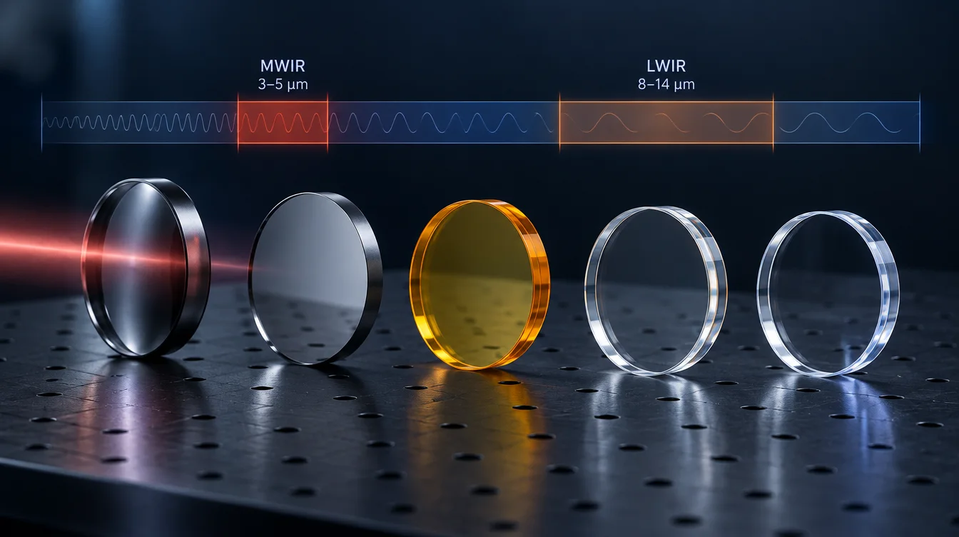
Short answer: To choose an infrared optical material, start from the operating waveband and detector, then confirm low absorption at the real thickness and temperature. Next, account for refractive index (reflection loss, AR coating, design freedom) and dn/dT (thermal focus shift). Finally, match hardness and environmental resistance to the exposure, and weigh weight, manufacturing route, volume and cost. No single material wins on all six.
Germanium, silicon, zinc selenide (ZnSe), zinc sulfide (ZnS), chalcogenide glass, sapphire and the fluoride crystals all transmit somewhere in the infrared, but they behave very differently once a lens heats up, a window faces sand and rain, or a CO2 laser passes through at high power. This guide walks through the selection order engineers actually use, with typical material data from manufacturer datasheets, worked examples and an RFQ checklist.
How to choose an infrared optical material: six checks in order
- Waveband and detector — SWIR, MWIR, LWIR, a laser line, or several bands at once.
- Absorption at the real thickness and temperature — not just the edge of the datasheet transmission range.
- Refractive index and dispersion — Fresnel reflection loss, AR coating design, and how many elements the lens needs.
- Thermal behavior — dn/dT, thermal expansion and the resulting focus shift over the operating temperature range.
- Mechanical and environmental durability — hardness, erosion, water solubility, thermal shock, birefringence.
- Manufacturability, weight, volume and supply — polishing versus diamond turning versus molding, density and cost.
The order matters. A material that fails step 1 or 2 cannot be rescued by a good coating or a clever mount, while weaknesses found in steps 4–6 can often be managed by design.
Step 1: Start from the waveband and the detector
The detector defines the band that has to reach the focal plane, and the material only needs to perform well inside that band. Typical system bands are:
- SWIR (about 0.9–1.7 µm) — InGaAs cameras and many laser sensing systems. Optical glasses, fused silica, sapphire and CaF2 are common; dedicated IR crystals are often unnecessary.
- MWIR (about 3–5 µm) — cooled InSb or HgCdTe cameras, gas sensing, some pyrometry. Silicon, germanium, sapphire, CaF2, ZnS and ZnSe are all candidates.
- LWIR (about 8–14 µm) — uncooled microbolometer thermal cameras. Germanium, ZnSe, ZnS and chalcogenide glasses dominate; silicon and sapphire are generally not suitable here.
- CO2 laser (10.6 µm) — absorption, not just transmission, decides the material, which is why ZnSe is the usual transmissive choice.
Datasheet “transmission ranges” describe where a material transmits at all, usually for a thin uncoated sample at room temperature. The useful range for a thick, coated element at operating temperature is narrower, so treat the range as a first filter only.
Infrared optical material comparison
| Material | Typical transmission range | Refractive index (approx.) | Main strengths | Main watch-outs |
|---|---|---|---|---|
| Germanium (Ge) | ~2–14 µm in practice (datasheets list up to ~23 µm) | ~4.0 (MWIR–LWIR) | Very high index, low dispersion in LWIR, good hardness for an IR crystal | Strong temperature sensitivity (dn/dT, thermal runaway), heavy, high reflection loss uncoated |
| Silicon (Si) | ~1.2–7 µm for most optical use | ~3.42 | Low density, high thermal conductivity, hard, cost-effective for MWIR | Oxygen-related absorption near 9 µm in Czochralski-grown material; not a standard LWIR imaging material |
| Zinc selenide (ZnSe) | Red visible to ~16 µm | ~2.40 at 10.6 µm | Very low absorption at 10.6 µm, transmits visible light for alignment, moderate dn/dT | Soft and easily scratched; needs protection when exposed; controlled dust handling during processing |
| Zinc sulfide, standard CVD (ZnS) | Mainly used 8–12 µm (also MWIR) | ~2.19 at 10.6 µm | Harder than ZnSe, good for exposed LWIR windows and domes | Higher absorption and scatter than ZnSe; not suited to high-power CO2 lasers |
| Zinc sulfide, multispectral grade | ~0.4–12 µm | ~2.20 at 10 µm | Water-clear; one window for visible, NIR, MWIR and LWIR channels | Softer than standard ZnS; higher cost |
| Chalcogenide glasses | LWIR, often also MWIR (composition-dependent) | ~2.4–2.8 at 10 µm | Can be molded for volume production; several grades have low dn/dT for athermal design | Higher thermal expansion; properties vary strongly by composition |
| Sapphire (Al2O3) | ~0.17–5.5 µm | ~1.6–1.7 in MWIR | Very hard, chemically resistant, robust MWIR window | Absorption rises toward 5 µm; birefringent; hard to machine |
| Calcium fluoride (CaF2) | ~0.13–10 µm | ~1.4 | Low index, low reflection loss, UV to MWIR | Sensitive to thermal shock; softer than oxide crystals |
| Barium fluoride (BaF2) | ~0.15–12 µm | ~1.40 at 10 µm | Low index with transmission further into LWIR than CaF2 | Highly susceptible to thermal shock; slightly water-soluble |
| Magnesium fluoride (MgF2) | ~0.12–7 µm | ~1.35–1.38 | Durable, resistant to chemical etching, UV to MWIR | Birefringent; limited LWIR use |
| IR-grade fused silica | ~0.2–3.5 µm | ~1.4–1.45 | Excellent for NIR/SWIR, mature processing | OH absorption near 2.7 µm in standard grades; no MWIR/LWIR |
Typical values compiled from material manufacturers’ public datasheets (see references). Exact values depend on grade, growth method, thickness, wavelength and temperature; use the supplier’s certificate for design.
For deeper comparisons of specific pairs, see ZnSe vs germanium for infrared lenses, germanium vs silicon for MWIR and LWIR optics and ZnSe vs ZnS infrared optics.
Step 2: Check absorption at the real thickness and temperature
Bulk absorption reduces internal transmittance exponentially with thickness:
Tinternal = exp(−α · d)
where α is the absorption coefficient at the operating wavelength and d is the thickness. A material that looks fine as a 2 mm window can be a poor choice for a 10 mm lens or a high-power laser element.
Illustrative example at 10.6 µm, 10 mm thick: using the upper-bound absorption values from one manufacturer’s datasheet, CVD ZnS (α < 0.24 cm−1) gives an internal transmittance of roughly 79% or better, while CVD ZnSe (α < 0.0005 cm−1) stays above 99.9%. The difference is not just lost signal: absorbed laser power becomes heat inside the optic, which is why ZnSe is the standard transmissive material for CO2 laser lenses and windows. More background is in how material absorption affects optical transmission.
Temperature and material grade matter as much as the material name:
- Germanium is subject to thermal runaway: as temperature rises, thermally generated free carriers increase absorption, which heats the part further. Suppliers commonly recommend keeping germanium optics below about 100 °C in use. Check this for windows near hot exhaust, lamps or laser beams (see thermal lensing in germanium optics).
- Silicon grown by the Czochralski (CZ) method shows an oxygen-related absorption band around 9 µm. Float-zone (FZ) material reduces but does not eliminate it. This is one reason silicon is normally a 3–5 µm material rather than an 8–14 µm imaging material.
- Fused silica grades differ by OH content; standard grades absorb near 2.7 µm, so specify an IR grade if the band extends past about 2.5 µm.
- ZnS grades differ: standard CVD ZnS and multispectral ZnS are not interchangeable in transmission, hardness or cost.
Step 3: Account for refractive index, reflection loss and AR coating
At normal incidence, the reflection from one uncoated surface is:
R = ((n − 1) / (n + 1))²
| Material | Index used | Reflection per uncoated surface | Two-surface transmission (no absorption, incl. multiple reflections) |
|---|---|---|---|
| Germanium | 4.0 | 36% | ~47% |
| Silicon | 3.42 | 30% | ~54% |
| ZnSe | 2.40 | 17% | ~71% |
| ZnS | 2.19 | 14% | ~76% |
| CaF2 / BaF2 | 1.40 | ~2.8% | ~95% |
Calculated values for illustration at normal incidence; actual transmission also depends on wavelength, absorption, AOI and coating.
Three practical consequences follow:
- AR coating is effectively mandatory for high-index materials. An uncoated germanium window loses more than half the signal. The coating must be designed for the actual band (for example 3–5 µm, 8–12 µm or dual-band) and AOI; a coating optimized for one band can perform poorly in another.
- Exposed surfaces need durable coatings. Hard carbon (DLC-type) coatings are commonly used on the outer surface of germanium windows and lenses in LWIR systems; their durability should be verified against the environmental tests the project actually requires.
- High index gives design freedom. A high-index material needs less surface curvature for the same optical power, which reduces aberrations and can cut element count. Germanium’s low dispersion in the LWIR adds to this, which is why it is widely used for thermal lenses, often combined with ZnSe or chalcogenide elements for color correction.
Step 4: Evaluate thermal behavior and focus shift
Infrared materials can have very large thermo-optic coefficients. For a single thin lens in air, the relative change of focal length with temperature can be estimated as:
(1/f) · df/dT ≈ αL − (dn/dT) / (n − 1)
where αL is the linear thermal expansion coefficient. Applying this to a 50 mm focal length lens over a 40 K temperature change gives the following illustrative comparison:
| Material (LWIR) | n | dn/dT (×10−6/K) | αL (×10−6/K) | Approx. focal shift, f = 50 mm, ΔT = 40 K |
|---|---|---|---|---|
| Germanium | 4.00 | 396 | 6.1 | ~−0.25 mm |
| ZnSe | 2.40 | 61 | 7.6 | ~−0.07 mm |
| Chalcogenide (one commercial grade, IRG 26) | 2.78 | 32 | 21.4 | ~+0.007 mm |
Thin-lens, lens-only estimate for illustration. Real systems must also include housing and spacer expansion, detector position and multi-element interactions.
For scale, the depth of focus of an f/1 lens at 10 µm is roughly ±2λN² ≈ ±20 µm. A 0.25 mm focus shift in a germanium singlet is therefore an order of magnitude larger than what the detector can tolerate. This does not rule out germanium; it means the design needs athermalization, either mechanical (housing materials chosen to compensate), active (motorized refocus) or optical (combining materials with different dn/dT). Low-dn/dT chalcogenide grades are often chosen precisely to make passive athermalization easier. Silicon in the MWIR sits between these cases, with dn/dT around 160×10−6/K.
Thermal shock is a separate issue. CaF2 and especially BaF2 can crack under rapid temperature changes, while silicon’s high thermal conductivity helps it spread local heating from a beam.
Step 5: Match durability to the operating environment
A lens inside a sealed housing and a window facing the outside world need different materials, even in the same band.
- Hardness and erosion: Knoop hardness values from manufacturer datasheets are roughly 1150 for silicon, 780 for germanium, 210–240 for standard CVD ZnS and 105–120 for ZnSe. Sapphire is harder than all of these. For an exposed LWIR window, standard ZnS or coated germanium is usually preferred over bare ZnSe.
- Moisture and chemicals: BaF2 is slightly water-soluble; humid or condensing environments need protection or another material.
- Birefringence: Sapphire and MgF2 are birefringent crystals. For polarization-sensitive systems or imaging through thick parts, crystal orientation must be specified. See sapphire vs fused silica optical windows for the window case.
- Weight: Germanium (5.33 g/cm³) and ZnSe (5.27 g/cm³) are heavy; silicon (2.33 g/cm³) is less than half that, which matters in handheld, drone and gimbal systems.
Step 6: Weigh manufacturability, volume and supply
- Processing route: Crystalline materials such as germanium, silicon and ZnSe are conventionally ground and polished, and are also commonly single-point diamond turned to produce aspheric or diffractive surfaces. Chalcogenide glasses can be precision-molded, which suits high-volume thermal camera lenses.
- Size and form: Available blank sizes, single-crystal versus polycrystalline material and thickness limits differ by material and supplier; confirm them early for large windows or thick lenses.
- Cost and lead time: Germanium pricing and availability have historically been sensitive to raw material supply. Confirm current pricing and lead time at the RFQ stage rather than relying on past quotes.
Typical starting points by application
| Application | Band | Common starting materials | Key deciding factor |
|---|---|---|---|
| Uncooled thermal camera lens | 8–14 µm | Germanium, chalcogenide, ZnSe | Athermalization, volume, cost |
| Exposed LWIR protective window | 8–12 µm | Germanium with hard coating, standard ZnS | Erosion resistance, coating durability |
| Cooled MWIR camera optics | 3–5 µm | Silicon, germanium (often combined), CaF2 | Weight, color correction, thermal stability |
| CO2 laser lenses and windows | 10.6 µm | ZnSe; germanium for some output and low-power optics | Bulk absorption and thermal lensing at power |
| Multi-sensor window (visible + IR) | 0.4–12 µm | Multispectral ZnS | One aperture for several channels |
| NDIR gas sensing windows | ~3–5 µm | Sapphire, silicon, CaF2, germanium | Target absorption line, filter integration, cost |
| SWIR imaging and laser sensing | 0.9–1.7 µm | Optical glass, fused silica, sapphire | Detector band, laser line, coating |
General engineering starting points, not final selections. Confirm against the full requirement set above.
For a worked example of a single material choice, see how to choose a silicon lens for infrared systems.
Common mistakes when choosing an infrared material
- Selecting from the edge of the transmission range. Performance near the edge is sensitive to thickness, temperature and grade.
- Ignoring the operating temperature. A germanium design verified only at 20 °C can lose focus or transmission in the field.
- Specifying the material name but not the grade. CZ vs FZ silicon, standard vs multispectral ZnS, and fused silica OH grades behave differently.
- Using silicon for 8–14 µm thermal imaging because it “transmits infrared” in general.
- Placing bare ZnSe as an exposed outer window where sand, wiping or rain will scratch it.
- Treating the AR coating as an afterthought. For high-index materials, the coating band and durability can decide system performance as much as the substrate.
How to verify the material and the finished part
- Material documentation: request the material type, grade and, where relevant, growth method (for example FZ or CZ silicon), plus any inclusion or homogeneity requirements.
- Spectral transmission: measure with an FTIR or spectrophotometer over the specified band, stating whether the result is for the coated part or a witness sample, the AOI and the temperature.
- Temperature behavior: for germanium windows or athermal lens designs, verify transmission or focus at the operating temperature extremes if the system is sensitive to them.
- Surface and coating: specify surface quality, scatter where relevant, and the coating durability tests (adhesion, abrasion, humidity) by the method named in the drawing, such as ISO 9211-4 or the customer’s own specification.
What to send with an RFQ for infrared optics
- Operating waveband and detector type (or laser wavelength and power)
- Preferred material and grade, or the constraints if the material is still open
- Drawing with dimensions, thickness, surface figure, surface quality and tolerances
- AR or protective coating band, AOI and required transmission or reflection
- Operating and storage temperature range, and whether the part is exposed to the environment
- Inspection and acceptance criteria, including test conditions
- Expected quantity and whether this is a prototype or production project
Working with GIAI Photonics on infrared optics
GIAI Photonics supplies custom infrared optics, including lenses, windows and filters. Materials listed on our current manufacturing capabilities page include silicon, germanium, ZnSe, sapphire and MgF2, among other optical materials. Achievable sizes, tolerances and coatings depend on the material and the part, so we review each project against the drawing, optical requirements, material, geometry, coating conditions and inspection criteria before defining the manufacturing route. For other infrared materials, feasibility is reviewed case by case. More material articles are collected in our Optical Materials & Infrared resources.
FAQ
Is germanium always the best material for LWIR lenses?
No. Germanium offers a very high refractive index and low LWIR dispersion, which simplifies lens design, but its dn/dT is very large and it is heavy and costly. Chalcogenide glasses are often chosen for high-volume, passively athermalized thermal camera lenses, and ZnSe is common as a second element for color correction. The best choice depends on temperature range, volume and cost targets.
Can silicon be used for 8–12 µm thermal imaging?
Generally not as a main imaging material. Silicon transmits well from about 1.2 to 7 µm, but Czochralski-grown silicon has an oxygen-related absorption band near 9 µm, and transmission across the LWIR is not competitive with germanium, ZnSe or chalcogenide glass. Silicon is a strong choice for 3–5 µm systems, especially where weight matters.
Why is ZnSe preferred for CO2 laser optics?
Its bulk absorption at 10.6 µm is extremely low, so very little laser power is converted to heat inside the optic. That limits thermal lensing and damage risk at high power. ZnSe also transmits red visible light, which helps with alignment using a visible pilot beam. Its main weakness is softness, so it is usually used inside protected beam paths.
Should a window use the same material as the lens behind it?
Not necessarily. The window’s job is to transmit the band while surviving the environment, so hardness, erosion resistance and coating durability often decide. A thermal camera may use germanium or chalcogenide lenses internally with a hard-coated germanium or standard ZnS window outside. Remember that a thick window also adds absorption and, for high-index materials, reflection loss that must be coated away.
Does the AR coating change which material I should choose?
It can. High-index materials such as germanium and silicon depend on AR coatings to reach useful transmission, and the coating must match the band, AOI and environment. If a system needs a very broad or dual band, or a durable outer coating, the achievable coating performance on each candidate material should be checked before the substrate is fixed.
Selecting an infrared material for a new design? Send the waveband, drawing or sample, material preference, coating requirements, AOI, operating temperature range, inspection criteria and expected quantity to our engineering team through the contact page for a technical review.
References
- Crystran, Germanium (Ge) data sheet
- Crystran, Silicon (Si) data sheet
- Crystran, Barium Fluoride (BaF2)
- Coherent, Optical materials data sheet: ZnSe, ZnS and multispectral ZnS
- SCHOTT, Technical details of infrared chalcogenide glasses (IRG series)
- Edmund Optics, Germanium (Ge) windows: thermal runaway and use temperature