
Technical Resources
How Beamsplitter Ratio Is Defined: R:T, AOI and Polarization
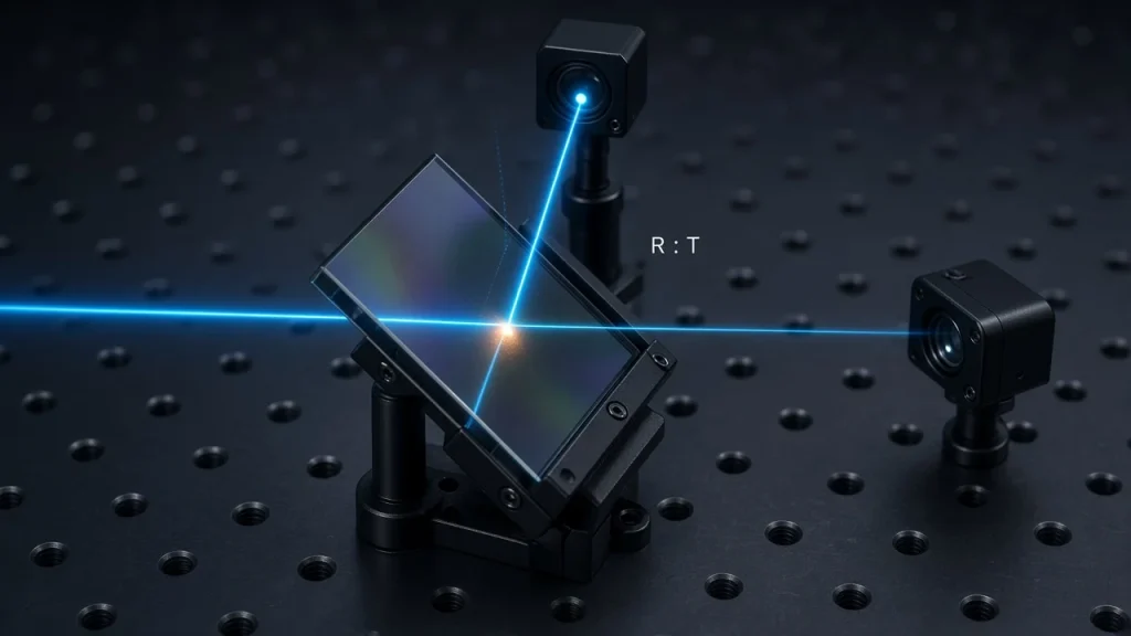
A beamsplitter ratio is defined as the fraction of incident optical power that leaves the component as the reflected beam (R) and as the transmitted beam (T), usually written R:T in percent, such as 30:70. The figures are only meaningful together with their test conditions: wavelength or band, angle of incidence, polarization state and tolerance. Because absorption and scatter take a share of the light, R and T add up to slightly less than 100% for dielectric coatings and noticeably less for metallic ones.
Most engineers know what “50:50” is supposed to mean. The trouble starts when a part that met its datasheet gives the wrong power balance in a real system. In almost every case the ratio itself was fine; the conditions behind it were different from the ones in the application. This article explains how the split ratio is defined, which conditions belong to it, how its tolerance is written and how it is checked. For the basics of how beamsplitters work, see What Is a Beamsplitter and How Does It Work?
How Beamsplitter Ratio Is Defined: R and T as Fractions of Incident Power
The split ratio is built from two quantities, both referenced to the same incident beam:
R = Preflected / Pincident T = Ptransmitted / PincidentEnergy conservation adds a third term that the ratio does not show directly:
R + T + A + S = 1where A is absorption and S is scatter. For a well-made all-dielectric coating on a transparent substrate, A and S are small, so R + T is close to 100% and the shorthand “R:T = 30:70” is a fair description. For metallic or metal-dielectric hybrid coatings, absorption is a real part of the budget. Such parts may be listed with R and T values that clearly sum to less than 100%, and the missing power turns into heat in the coating.
Two consequences follow. First, the ratio describes power (radiant flux), not irradiance; two beams with equal power can still have different irradiance on a detector if their footprints differ. Second, R and T are fractions of the input, not of the total output. That is a different convention from fiber couplers, where the coupling ratio is usually the power in one output port divided by the total output power, and losses are reported separately as excess loss. Applying the fiber convention to a free-space metallic beamsplitter would make the absorption disappear from the specification.
R:T or T:R? Why the Order Must Be Stated
There is no single industry convention for which number comes first. Many catalogs write R/T, others write T:R, and both appear on GIAI’s own beamsplitter product listings. A drawing that says only “30:70” can therefore be built either way, and the two parts are not interchangeable.
| Written on the drawing | Reflected power | Transmitted power | Risk |
|---|---|---|---|
| R:T = 30:70 | 30% | 70% | Clear, if the label “R:T” is kept with the numbers |
| T:R = 30:70 | 70% | 30% | Opposite part from the line above |
| 30:70 (no label) | Unknown | Unknown | Either part can be supplied “to drawing” |
| R = 30%, T = 70% | 30% | 70% | Least ambiguous form |
For cube beamsplitters, also identify the entrance face and which exit face is the “reflected” port, because a cube can be installed rotated or reversed without any visible difference.
The Conditions That Make a Split Ratio Meaningful
Wavelength or wavelength band
A coating’s R and T vary with wavelength. A ratio given at 532 nm says nothing about 633 nm. For broadband parts, state whether the tolerance applies to the average over the band or to every wavelength in the band. An average specification can hide strong ripple, which matters for spectrally resolved measurements or for sources with narrow emission lines.
Angle of incidence (AOI)
Plate beamsplitters are commonly designed for 45° AOI; cube beamsplitters are used at normal incidence on the entrance face with a 45° internal hypotenuse. Thin-film behavior is angle-dependent, so the ratio moves when the part is tilted away from its design angle. In a converging or diverging beam, the coating sees a spread of angles and the effective ratio is an average over that cone. If the optical layout does not use the design AOI, the specification should be written at the AOI actually used.
Polarization state
At oblique incidence the coating reflects s- and p-polarized light differently. In most conventional dielectric designs at 45°, Rs is higher than Rp. A ratio quoted for “unpolarized” or “random” light is the average of the two:
Runpol = (Rs + Rp) / 2For linearly polarized light whose polarization direction makes an angle ψ with the plane of incidence, the reflected fraction is:
R(ψ) = Rp cos2ψ + Rs sin2ψHypothetical example (not a product specification): a lossless plate with Rs = 60% and Rp = 40% meets “50:50 unpolarized”. Used with a p-polarized laser, the same part reflects about 40% and transmits about 60%. Nothing is wrong with the part; the specification simply described a different input.
For polarized sources, specify R and T for the actual polarization, or use a non-polarizing design and limit the s/p difference directly, for example as a maximum |Ts − Tp|. The trade-offs are covered in How S and P Polarization Affect Beamsplitter Selection and Polarizing vs Non-Polarizing Beamsplitter.
Coating-level or component-level values
A plate beamsplitter has a splitting coating on one face and usually an anti-reflection (AR) coating on the other. Transmitted power measured through the whole plate includes the residual reflection of the AR face and any substrate absorption. On the reflected side, the AR face also produces a weak, displaced secondary beam that may or may not fall inside the detector aperture. State whether R and T refer to the coated surface alone or to the finished component in its working geometry. The secondary reflection itself is discussed in What Causes Ghost Images in Beamsplitters?; the geometry differences between plates and cubes are in Cube Beamsplitter vs Plate Beamsplitter.
How the Split Ratio Tolerance Is Written
A tolerance written as “T = 50% ± 5%” is normally read as ±5 percentage points, meaning T between 45% and 55%. Some readers interpret it as ±5% of the value, meaning 47.5% to 52.5%. The two differ by a factor of two, so write “±5 percentage points” or give the explicit range.
Decide also what the tolerance protects:
- Tolerance on R and T separately suits power-budget designs where each arm must receive a minimum level.
- Tolerance on the ratio R/T suits balanced or differential detection, where the balance matters more than the absolute values. For a lossless coating, R/T = 1.00 ± 0.10 corresponds to R from about 47.4% to 52.4%, which is tighter than R = 50% ± 5 percentage points.
- Band treatment: average over the band, or every wavelength inside it.
The table below summarizes what a complete ratio specification contains and what goes wrong when an item is left out.
| Specification item | What to state | Typical problem when omitted |
|---|---|---|
| Ratio and order | R = __%, T = __% (or R:T with the label) | Part supplied with reflection and transmission swapped |
| Wavelength | Single wavelength or band; average or each wavelength | Ratio correct at one wavelength, off at the working line |
| AOI | Working angle and, if relevant, beam cone angle | Ratio shifts after the part is mounted at a different angle |
| Polarization | Unpolarized average, s, p, or a stated linear orientation | Polarized laser sees a very different split |
| Tolerance | Absolute percentage points or explicit range; on R, T, or R/T | Supplier and buyer accept against different limits |
| Losses | Maximum absorption or minimum R + T, where relevant | Unexpected heating or missing power with metallic coatings |
| Reference level | Coating surface only, or complete component including AR face | Measured T lower than expected; secondary reflection counted or not |
How to Verify a Beamsplitter Split Ratio
- Match the test to the specification. Measure at the specified AOI, wavelength range and polarization. For s and p values, place a polarizer in the measurement beam.
- Measure both T and R when losses are not negligible. With a spectrophotometer, transmittance is straightforward; absolute reflectance needs an accessory set to the working angle. Calculating R as 1 − T is only acceptable for low-loss dielectric coatings, and never for metallic or absorbing designs.
- Check at the operating wavelength with a power meter. Record Pincident, Preflected and Ptransmitted with the same calibrated detector, capture each beam completely and keep the detector in its linear range. The sum R + T gives a quick estimate of loss.
- Record the conditions on the report. A ratio without AOI, polarization, wavelength and sample identification cannot be compared with a drawing.
Coating runs are often qualified on witness samples coated alongside the parts. If acceptance must be based on the finished component instead, state this on the drawing, because the measurement setup and the result can differ.
Common Misunderstandings About Split Ratio
- “50:50 works for any light source.” It holds only under the polarization, wavelength and AOI for which it was specified.
- “R + T always equals 100%.” Close for good dielectric coatings, not for metallic ones.
- “Tilting the plate a few degrees is harmless.” It changes the effective AOI and can move the ratio, especially for polarized light.
- “Everyone writes R first.” Many do, but not all suppliers or documents follow that order.
What to Include When Requesting a Custom Beamsplitter
- R and T with explicit order, tolerance type and limits
- Wavelength or band, and whether the tolerance applies to the band average or each wavelength
- Working AOI and beam cone angle
- Source polarization and its orientation relative to the plane of incidence
- Plate or cube, substrate, dimensions, clear aperture and second-surface AR requirement
- Maximum absorption or minimum R + T, if power loss or heating matters
- Acceptance method: test setup, wavelength points and whether witness samples are acceptable
GIAI Photonics reviews custom beamsplitter projects against the drawing, sample or optical specification, together with the substrate, geometry, coating conditions and inspection criteria, before defining the manufacturing route. See the custom optics process for how a project moves from specification to production.
FAQ
Does a beamsplitter have the same split ratio from both sides?
For transmittance, thin-film theory says yes: T through a coating is the same in both directions. For a non-absorbing dielectric coating, R is also the same from either side. For absorbing coatings such as metal films, reflectance differs between the two sides. With a plate beamsplitter, reversing it also changes the beam offset and the order in which the AR face and coating are met, so the system behavior can change even when the coating values do not.
Is split ratio the same as extinction ratio?
No. Split ratio describes how power divides between the reflected and transmitted beams. Extinction ratio is a polarizing-beamsplitter figure that compares wanted and unwanted polarization in an output beam, for example Tp/Ts in the transmitted arm. A non-polarizing beamsplitter is specified by split ratio and s/p difference instead.
Can one beamsplitter have different ratios at different wavelengths?
Yes. Each band can be given its own R and T with its own tolerance. When the ratio changes deliberately from mostly reflecting to mostly transmitting across the spectrum, the part is functioning as a dichroic beamsplitter, and it is specified by edge position and band limits rather than a single ratio.
Why does my measured ratio differ from the datasheet?
The usual causes are a different AOI, a polarized source measured against an unpolarized specification, a wavelength outside the specified band, a converging beam, or a detector that clips one of the beams. Repeat the measurement under the datasheet conditions first; if it then agrees, the specification needs to be rewritten for the real system.
Planning a custom beamsplitter? Send the drawing or optical specification with R and T (order and tolerance), wavelength band, AOI, polarization, dimensions, substrate and acceptance method to the GIAI engineering team for technical review.
References for general optics: H. A. Macleod, Thin-Film Optical Filters (CRC Press), on reflectance, transmittance, absorption and reciprocity in multilayer coatings; E. Hecht, Optics (Pearson), on Fresnel reflection for s- and p-polarized light; ISO 10110-9, on indicating surface treatments and coatings on optical drawings.