
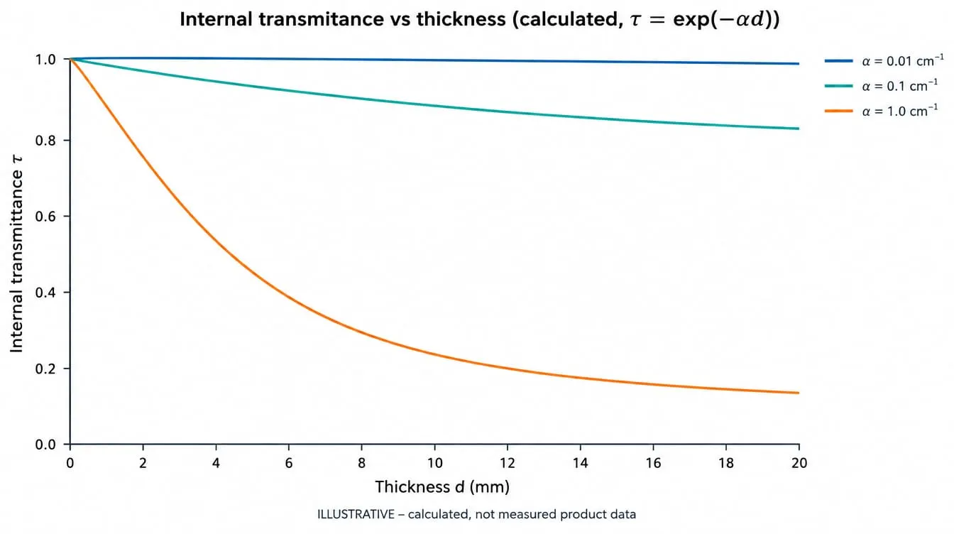
- Internal transmittance falls exponentially with path length, τ = exp(−αd); doubling thickness squares τ, and the loss doubles only while absorption is weak.
- Uncoated glass at n = 1.5 transmits at most 92.3% at normal incidence (calculated); that gap is reflection, not absorption.
- A transmission reading alone cannot separate absorption, reflection and scatter; each needs its own measurement or model.
- The two-thickness method recovers α, but high-index materials such as germanium need the full multiple-reflection model.
- An absorption requirement is incomplete without wavelength, thickness, AOI, temperature and whether transmission is internal or external.
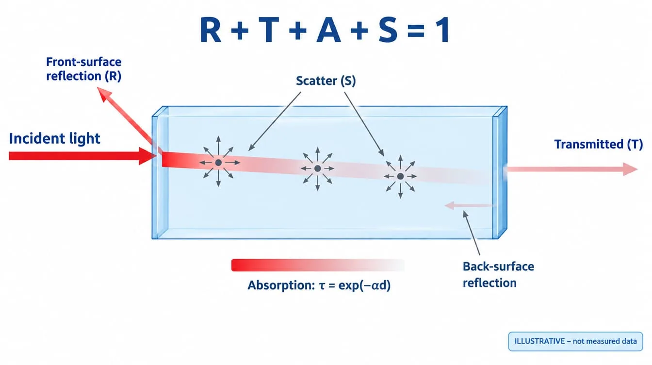
Material absorption reduces optical transmission exponentially with path length: the internal transmittance of a homogeneous material equals exp(−αd), where α is the absorption coefficient at the wavelength of interest and d is the path length. Measured transmission is lower still, because surface reflection and scatter remove light that was never absorbed. Verifying absorption means separating these three losses.
The distinction matters whenever a window, lens, filter substrate or infrared element misses its transmission target and the cause has to be assigned to the material, the surface or the coating. Unless a section states otherwise, the relations below assume normal incidence, incoherent light (no etalon fringes), a homogeneous isotropic material, parallel polished surfaces and an extinction coefficient k much smaller than the refractive index n.
What happens to light that enters an optical material?
At each wavelength, light arriving at an optical plate is reflected, transmitted, absorbed or scattered, and the four fractions sum to one: R + T + A + S = 1. Absorption converts optical energy into heat, or in some materials into fluorescence. A transmission measurement reports only T, so a low reading does not say which of the other three terms removed the missing light.
Three terms are often confused on datasheets. Absorptance is the dimensionless fraction of incident power absorbed by a component. Absorbance is logarithmic, normally the decadic value −log10 of internal transmittance. The absorption coefficient α, in cm−1 with base e, is a material property independent of sample thickness. It is linked to the extinction coefficient k of the complex refractive index by α = 4πk/λ0, where λ0 is the vacuum wavelength. In chemistry, “extinction coefficient” usually means molar absorptivity instead, so confirm which quantity a source is using before converting.
How does absorption scale with material thickness?
Inside a homogeneous material, intensity decays exponentially with path length, so internal transmittance is τ = exp(−αd). This is the Beer–Lambert–Bouguer relation. Each additional millimeter removes the same fraction of the light that remains, and doubling the thickness squares τ.
When αd is small, 1 − τ is close to αd and the loss appears to grow linearly. That approximation fails as αd approaches 0.1 and above. The table shows how the same thickness change produces very different outcomes depending on α, and how reflection dominates the loss of a weakly absorbing plate.
| α (cm⁻¹) | τ at 2 09 | τ at 10 09 | T at 10 09 |
|---|---|---|---|
| 0.001 | 0.9998 | 0.9990 | 0.9222 |
| 0.01 | 0.9980 | 0.9900 | 0.9139 |
| 0.1 | 0.9802 | 0.9048 | 0.8350 |
| 1.0 | 0.8187 | 0.3679 | 0.3391 |
Calculated values, not measured product data. τ = internal transmittance. T = external transmittance of an uncoated plate with n = 1.5 in air, normal incidence, incoherent multiple reflections included, no scatter.
At α = 0.001 cm−1, a 10 09 plate loses 0.1% to absorption and 7.7% to surface reflection. At α = 1.0 cm−1, absorption dominates.
Converting between units avoids most thickness-scaling errors:
- Decadic absorbance is αd/ln 10 = 0.4343 αd.
- Attenuation in dB is 4.343 αd.
- Optical density on filter datasheets is normally −log10 of external transmittance, so it includes reflection unless the datasheet states otherwise.
Off normal incidence, the path inside the plate lengthens to d/cos θt, where θt is the refraction angle. At 45° AOI into n = 1.5, θt is 28.1° and the path is 1.134 d (calculated). Surface reflection also becomes polarization dependent at non-zero AOI.
Why does absorption depend so strongly on wavelength?
The absorption coefficient is a spectral property and can change by orders of magnitude across a material’s range. Every transparent material has a window bounded by electronic absorption at short wavelengths and lattice vibration (multiphonon) absorption at long wavelengths. Inside that window, impurities, defects and free carriers add extrinsic absorption bands.
Absorption bands are physically tied to dispersion through the Kramers–Kronig relations, which is why the refractive index changes steeply near an absorption edge. The table su09arizes the mechanisms by material class. Wavelength limits are omitted because they depend on grade, thickness and the transmission level used to define the edge; take them from the material manufacturer’s data for the specific grade.
| Material class | Short-λ limit | Long-λ limit | Extrinsic absorbers |
|---|---|---|---|
| Optical glasses | Electronic UV edge | Multiphonon IR edge | OH, transition-metal ions, radiation-induced color centers |
| Fused silica | Electronic UV edge | Multiphonon IR edge | OH content, which depends on grade and manufacturing route |
| Wide-bandgap crystals (sapphire, MgF₂) | Electronic UV edge | Multiphonon IR edge | Impurities and color centers |
| Semiconductors (Si, Ge) | Band-gap edge | Lattice absorption bands | Free carriers from doping and temperature |
In fused silica, the OH fundamental absorption lies near 2.7 µm, so a grade that performs well in the UV may not suit a mid-infrared window. Optical materials and infrared resources cover these material choices in more detail.
Temperature moves absorption as well. In semiconductors, the band gap narrows as temperature rises, so the absorption edge shifts to longer wavelengths. In germanium, the intrinsic carrier density rises with temperature, which increases free-carrier absorption in the long-wave infrared and lowers transmission. This behavior can become self-reinforcing, because the extra absorbed power heats the element further. That is a design constraint for infrared optics exposed to heat.
Ultraviolet or ionizing exposure can also create color centers that add absorption bands (solarization). If the application involves such exposure, transmission should be measured before and after a defined dose.
How do you verify absorption loss instead of inferring it from transmission?
Verifying absorption requires measuring or modeling each loss term separately, under conditions that match the application. The practical sequence is:
- Define the quantity.
- Remove reflection by model or measurement.
- Extract α from thickness dependence.
- Isolate scatter.
- Switch to direct absorptance methods when absorption falls below photometric resolution.
Define internal or external transmittance
Glass manufacturers co09only tabulate internal transmittance at stated reference thicknesses, while a spectrophotometer measures external transmittance through the real part. A specification that says “T > 90%” without naming the quantity, thickness and AOI cannot be verified unambiguously.
Remove Fresnel reflection with a model
For an uncoated, non-scattering plate with incoherent multiple reflections:
- External transmittance is T = (1 − R)²τ / (1 − R²τ²).
- Single-surface reflectance at normal incidence is R = ((n − 1)/(n + 1))².
With τ = 1, this gives T = 92.3% for n = 1.5. For n = 4.0, a round value close to germanium in the long-wave infrared, it gives 47.1%. Both are calculated upper limits, not measured data. A low external reading on an uncoated high-index part is therefore expected even with negligible absorption.
The relation can be inverted to recover internal transmittance from a measured T:
τ = [√((1 − R)⁴ + 4R²T²) − (1 − R)²] / (2R²T)
Use two thicknesses to extract α
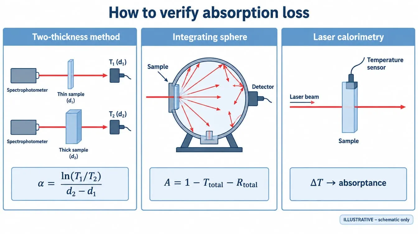
Measuring two samples of the same material at thicknesses d1 and d2 removes the reflection term, provided both samples share the same melt or batch, surface finish, cleanliness and parallelism.
For low-index materials, α = ln(T1/T2)/(d2 − d1) is sufficient. Worked example (calculated, not measured): with n = 1.5 and α = 0.050 cm−1, a 2 09 sample gives T1 = 0.9139 and a 10 09 sample gives T2 = 0.8779. The ratio formula returns α = 0.050 cm−1.
For high-index materials, the simple ratio overestimates α because the multiple-reflection denominator differs between the two samples. With n = 4.0 and α = 0.030 cm−1, samples of 3 09 and 10 09 give T = 0.4651 and 0.4528 (calculated). The simple ratio returns 0.039 cm−1, about 28% high. Converting each T to τ with the inversion above recovers 0.030 cm−1.
The example also exposes a measurement limit. The two readings differ by 1.2 percentage points. If the difference between samples is comparable to the instrument’s photometric repeatability, the extracted α is noise. The remedy is a larger thickness difference, not more averaging of one pair.
Separate scatter with an integrating sphere
A standard spectrophotometer records regular (specular) transmittance, so light scattered outside the detector’s acceptance is counted as loss. An integrating sphere collects total transmittance and total reflectance, and absorptance then follows from A = 1 − Ttotal − Rtotal. For scattering centers much smaller than the wavelength, Rayleigh scatter scales with λ−4. A loss that rises steeply toward the ultraviolet can therefore be scatter rather than an absorption edge, and only a sphere measurement distinguishes the two.
Measure low absorption directly
When absorptance is far below what a spectrophotometer can resolve, as with laser optics that must handle high average power, laser calorimetry measures the temperature rise of the part under a known beam power. ISO 11551 defines this test method. For coatings, absorptance is derived from T and R measured on the same part at the coating’s design wavelength, AOI and polarization. Tying these measurements to project-defined inspection and acceptance criteria keeps the result traceable.
What trade-offs does material absorption force in component design?
Lowering absorption loss usually costs something elsewhere: mechanical margin, blocking depth, coating complexity or thermal stability. The right balance depends on whether αd at the operating wavelength is actually a significant term next to reflection and scatter.
- Thickness versus mechanics. A thinner window absorbs less, but it deflects more under a pressure difference and is harder to hold flat during polishing and mounting. For optical windows that see a pressure load, thickness is set by the mechanical margin first, and absorption is checked afterwards.
- Blocking depth versus edge position in absorbing filters. In colored glass and absorptive neutral density filters, thickness sets the optical density. A thicker longpass glass blocks more deeply below the edge, but its 50% point moves to longer wavelengths and the glass absorbs more power as heat. The edge of colored glass filters also shifts with temperature. The filter and coating resources compare absorbing and interference designs.
- Reflection loss versus coating absorption. An AR coating removes most of the surface reflection loss but adds thin-film layers with their own absorption. That absorption is small in the design band but rises near the coating materials’ ultraviolet absorption edge, and it matters under high laser power.
- Absorbed power versus optical stability. Absorbed laser power heats the element and creates a thermal lens through dn/dT and thermal expansion. In long-wave infrared imaging, an absorbing window also emits thermal radiation in proportion to its absorptance, which adds background to the detector signal.
Which mistakes lead to wrong conclusions about absorption?
Most wrong conclusions about absorption come from treating a single external transmission reading as a material property. The recurring errors are:
- Reading reflection as absorption. An uncoated n = 1.5 part at 92% does not have an 8% absorption problem.
- Scaling percent transmission linearly with thickness. Reflection does not scale with thickness and absorption scales exponentially, so convert to α before rescaling.
- Applying the two-thickness ratio to high-index materials. Without the multiple-reflection correction, α is overestimated.
- Blaming absorption for beam displacement. Lenses, wedged parts and curved surfaces can steer or refocus the beam partly off the detector, which looks like loss in a spectrophotometer built for flat samples.
- Misreading etalon fringes. Narrow-linewidth sources or high-resolution scans of thin, parallel plates show interference fringes that can be misread as absorption features.
- Comparing datasheet curves at different reference thicknesses. A curve at 10 09 and one at 2 09 are not comparable until both are converted to α.
- Ignoring temperature and exposure history. A room-temperature measurement does not represent a germanium window running hot or a glass after UV exposure.
What should a transmission or absorption specification state?
A transmission or absorption requirement is verifiable only when it names the quantity and every condition that changes it. The items below close the gaps that cause disputes at acceptance.
- Wavelength or band, and the measurement bandwidth.
- Whether the limit applies to internal transmittance, external transmittance, absorptance or α.
- Thickness, including the reference thickness if the value is taken from material data.
- AOI, polarization and beam geometry (collimated or converging cone).
- Operating temperature and any exposure conditions.
- Coated or uncoated state.
- Measurement method (spectrophotometer, integrating sphere or calorimetry), and whether a witness sample or the finished part is measured.
GIAI reviews custom optical projects against the drawing, sample, optical requirements, substrate, geometry, coating conditions and inspection criteria before defining the manufacturing route, and an absorption requirement stated this way can be reviewed directly against the material and coating choice.
FAQ
Does thicker glass absorb more light?
Yes. Thicker glass absorbs more light because internal transmittance follows τ = exp(−αd), so absorption loss grows with path length d. The growth is exponential: doubling the thickness squares τ. For polished optical glass inside its transparent range, the extra absorption from a few millimeters can be much smaller than the 7.7% reflection loss of two uncoated surfaces at n = 1.5 (calculated, normal incidence).
What is the difference between internal and external transmittance?
Internal transmittance is the fraction of light that survives the path through a material, excluding reflection at its surfaces; it depends only on the absorption coefficient and thickness. External transmittance is what a spectrophotometer measures through a real part, so it includes surface reflection losses. Glass manufacturers co09only tabulate internal transmittance, so a component specification needs to state which quantity applies.
What is the difference between absorbance and absorptance?
Absorptance is the fraction of incident optical power that a component absorbs, a dimensionless number between 0 and 1 that can be measured by calorimetry or derived from A = 1 − T − R − S. Absorbance is logarithmic, normally the decadic value −log10 of internal transmittance. An absorbance of 1 corresponds to 10% internal transmittance, so the two terms are not interchangeable on a specification.
How do you measure the absorption coefficient of an optical material?
The absorption coefficient of an optical material is co09only measured with the two-thickness method: two samples from the same batch, polished identically, are measured at the same wavelength, and α = ln(T1/T2)/(d2 − d1). This works directly for low-index materials. High-index materials such as germanium need the multiple-reflection correction first, and very low absorption requires laser calorimetry.
Does an anti-reflection coating reduce absorption?
An anti-reflection coating does not reduce bulk absorption in the substrate; it reduces the light lost to surface reflection, which raises external transmittance. The coating layers can add a small absorption of their own, which becomes relevant near the coating materials’ ultraviolet absorption edge and under high laser power. Verification compares transmittance and reflectance of the coated part at the design wavelength, AOI and polarization.
Why does light intensity decrease when light passes through a glass block?
Light intensity decreases through a glass block for three separate reasons: part of the light reflects at each surface, part is absorbed inside the glass and converted to heat, and part is scattered out of the beam by inclusions, bubbles or surface roughness. For uncoated glass at n = 1.5 and normal incidence, reflection alone removes 7.7% (calculated), which can exceed the absorption loss of a thin block.
References
- ISO 15368, Optics and photonics — Measurement of reflectance of plane surfaces and transmittance of plane parallel elements.
- ISO 11551, Optics and photonics — Lasers and laser-related equipment — Test method for absorptance of optical laser components.
- ISO 13696, Optics and optical instruments — Test methods for radiation scattered by optical components.
- SCHOTT AG, Technical Information TIE-35: Transmittance of optical glass.
- E. Hecht, Optics, Pearson.
- M. Born and E. Wolf, Principles of Optics, Cambridge University Press.
For a custom window, lens or filter where absorption affects the transmission budget, send the drawing, optical specification or sample together with the wavelength range, substrate, dimensions, coating requirements, AOI, inspection criteria and expected quantity for technical review.