
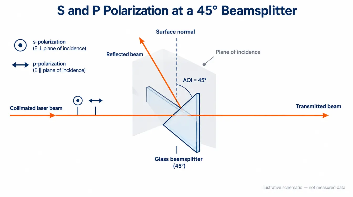
A beamsplitter does not treat s- and p-polarized light the same way. At any angle other than normal incidence, the reflectance of a surface or coating is higher for s-polarization than for p-polarization, and the difference grows with the angle of incidence. At 45°, the working angle of most plate and cube beamsplitters, this means a component described as “50/50” can deliver one split ratio for s-polarized light and a clearly different one for p-polarized light. If the source is a linearly polarized laser, the ratio you measure on the bench may not match the ratio on the datasheet — not because the coating is out of specification, but because the specification was written for a different polarization condition. Selecting a beamsplitter therefore starts with defining the polarization state of the input beam, not with the nominal split ratio.
What do s and p polarization mean at a beamsplitter surface?
The plane of incidence is the plane containing the incoming ray and the surface normal. Polarization is defined relative to that plane:
- s-polarization — the electric field oscillates perpendicular to the plane of incidence (from the German senkrecht). It is sometimes labelled TE.
- p-polarization — the electric field oscillates parallel to the plane of incidence. It is sometimes labelled TM.
Two consequences follow immediately. First, s and p are defined by the optical layout, not by the laser. Rotating the beamsplitter about the beam axis by 90° converts what was s-polarized input into p-polarized input, with no change to the coating. Second, at exactly 0° AOI there is no plane of incidence, so s and p are indistinguishable and the polarization splitting vanishes. Every polarization effect discussed below is a consequence of working at an angle.
Why does a 45° beamsplitter split s and p differently?
At each interface inside the component — substrate surface, every high- and low-index layer boundary in the coating — the boundary conditions imposed on the electric and magnetic fields depend on the field orientation. In thin-film design this appears as an effective index that takes different values for s and p once the angle is non-zero. The layer stack that produces a given reflectance for s therefore produces a different reflectance for p at the same wavelength.
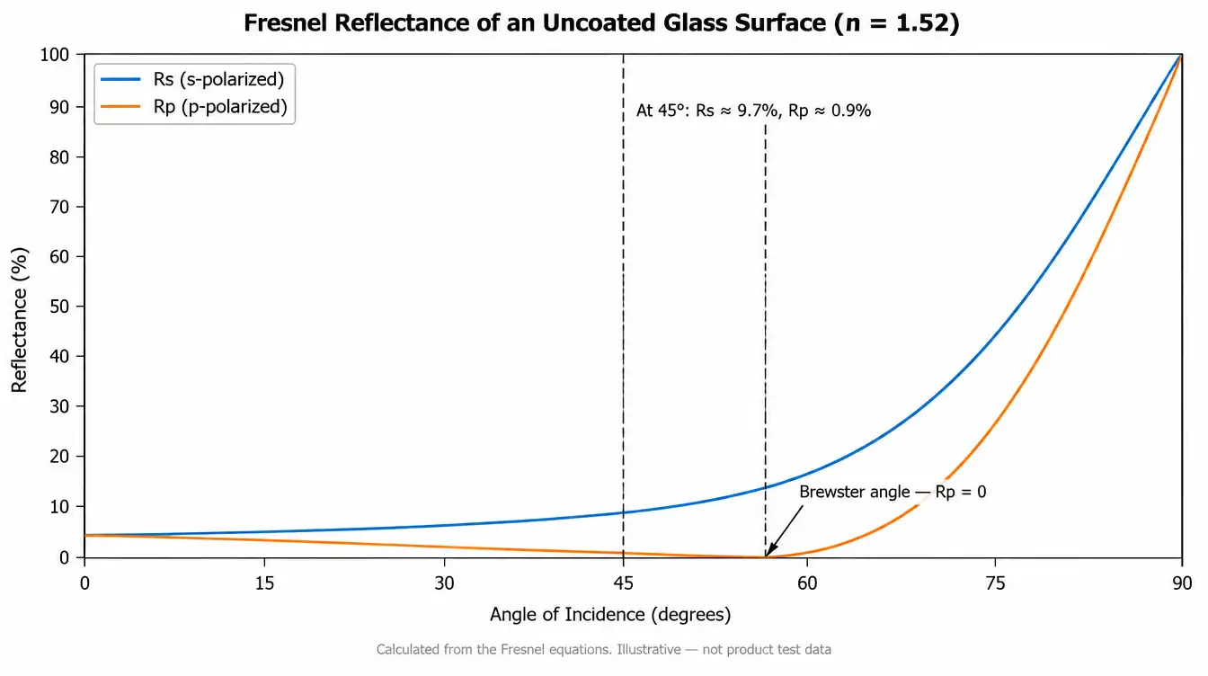
The effect is visible even without any coating. The table below gives Fresnel reflectance for a single uncoated air-to-glass surface at n = 1.52, calculated from the Fresnel equations. These are textbook values for a bare surface, shown to illustrate the trend, not measured product data.
| AOI | Rs | Rp | Rs − Rp |
|---|---|---|---|
| 0° | 4.3 % | 4.3 % | 0 |
| 30° | 6.1 % | 2.7 % | 3.4 points |
| 45° | 9.7 % | 0.9 % | 8.8 points |
| 56.7° (Brewster angle) | 15.7 % | 0 % | 15.7 points |
At 45° a bare surface already reflects roughly ten times more s than p. A dielectric beamsplitter coating multiplies this asymmetry across dozens of interfaces. Left uncorrected, a 45° dielectric stack is strongly polarizing; making it non-polarizing is an explicit design constraint that costs bandwidth, angular acceptance and layer count.
What does “non-polarizing” actually guarantee?
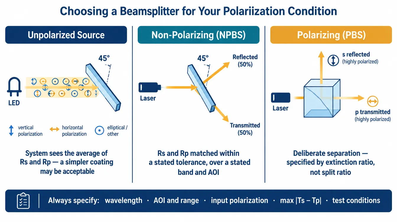
A non-polarizing beamsplitter (NPBS) is not one whose reflectance is independent of polarization. It is one whose s and p reflectance are forced to agree within a stated tolerance, over a stated wavelength band, at a stated angle of incidence. The specification is written as a maximum permissible difference — for example a limit on |Ts − Tp| or on the ratio Tp/Ts — and it is only valid inside those three conditions.
Three practical implications:
- A coating balanced at 45° drifts back toward polarizing behaviour at 43° or 47°. Mount tilt and beam pointing eat directly into the margin.
- A coating balanced from 450–650 nm gives no guarantee at 405 nm or 780 nm, even if average transmission there still looks acceptable.
- The residual difference is not zero. If your photometric budget needs the two channels matched to a fraction of a percent, the allowed |Ts − Tp| must be part of the acceptance criteria and must be measurable.
Metal and metal-dielectric hybrid coatings behave differently: their s/p difference is usually smaller than that of an all-dielectric stack and holds over a much wider band, but they absorb a fraction of the incident light, so transmission plus reflection does not sum to unity and heat is deposited in the coating. That absorption is what limits their use with high-power beams.
How do the common beamsplitter constructions compare?
| Construction | Polarization behaviour at 45° | Main limitation |
|---|---|---|
| Uncoated / partially coated plate | Strongly polarizing; Rs > Rp | Split ratio set by Fresnel, not by design intent |
| Dielectric NPBS plate | Balanced within tolerance over the design band and AOI | Narrower usable band and angular range; second-surface ghost unless wedged or AR-coated |
| Metallic / hybrid plate | Smaller s/p difference across a wide band | Absorption loss; limited power handling |
| Cemented NPBS cube | Balanced within tolerance; no beam deviation of the transmitted path | Cement layer limits power and wavelength range; longer glass path adds dispersion |
| MacNeille polarizing cube (PBS) | Deliberately polarizing: transmits p, reflects s | Narrow angular and spectral acceptance; reflected s channel is the cleaner one |
| Wire-grid polarizing beamsplitter | Deliberately polarizing over a broad band and wide angle | Grid structure is fragile and orientation-critical; contrast varies with wavelength |
| Pellicle | Polarizing unless coated for balance; very small ghost separation | Membrane is fragile and vibration-sensitive; wavefront limited |
A MacNeille cube exploits exactly the physics that an NPBS design fights: at the internal Brewster condition between the high- and low-index layers, p-polarized light passes with almost no reflection while s-polarized light is strongly reflected. Because that condition is angle-specific, the extinction ratio of a polarizing cube degrades quickly outside its acceptance cone.
What about the phase difference between s and p?
Amplitude is only half the story. Reflection from a coating also imposes a phase shift, and that shift is generally different for s and for p. A beam that is linearly polarized at 45° to the plane of incidence carries equal s and p components; after reflection those components are no longer in phase, and the output is elliptically polarized.
For a purely photometric application this is irrelevant. It matters when:
- the beamsplitter sits in an interferometer and the two arms must recombine with a defined polarization state;
- a downstream polarizer, PBS or polarimeter measures the state that the beamsplitter just modified;
- a quarter-wave plate and polarizer are used as an optical isolator and the beamsplitter’s retardance breaks the intended circular state;
- polarization-maintaining fibre is launched after the split.
Retardance between s and p is a separate specification from the split ratio. If it matters to the system, it has to appear on the drawing with its own tolerance and its own test condition, because a component that passes a 50/50 ratio check can still fail a polarization-state requirement.
How do AOI and beam convergence change the result?
Datasheet values assume a collimated beam at a single angle. Two departures are common in real systems.
Angle error
Mount tolerance, wedge in the mount and beam pointing drift all shift the working AOI. Since the s/p difference rises steeply with angle, a component specified at 45° ± 0° and used at 45° ± 3° may not meet its balance limit at the extremes. Specify the angular range you will actually operate over.
Converging or diverging beams
In an f/4 cone the rays span a range of incidence angles, so the split ratio varies across the pupil. Worse, skew rays define their own plane of incidence, rotated relative to the chief ray’s plane. What is pure s for the chief ray is a mixture for the edge rays, which means the beamsplitter both changes the ratio across the aperture and partially scrambles the polarization state. A plate beamsplitter in a converging beam also introduces astigmatism and a lateral shift proportional to thickness. Cubes avoid the astigmatism but add glass path.
What are the trade-offs you cannot design away?
None of these parameters improves in isolation; each is bought with another.
- Polarization balance vs. bandwidth. Forcing Rs and Rp together requires additional layers tuned to a narrower spectral window. A wide-band NPBS and a tightly matched NPBS are different designs, and asking for both at once usually means neither is met at the edges.
- Polarization balance vs. angular acceptance. Same mechanism. A design balanced over 45° ± 5° will generally show a larger residual difference at the nominal angle than one balanced at 45° only.
- Extinction ratio vs. acceptance cone. For a polarizing cube, high extinction depends on sitting at the internal Brewster condition. Widening the usable cone lowers the achievable contrast.
- Low absorption vs. spectral flatness. Metallic coatings give flatter polarization behaviour over a wide band but lose energy to absorption; dielectric stacks are efficient but more strongly polarizing and more angle-sensitive.
- Cube convenience vs. power and wavelength range. A cemented cube removes beam deviation and second-surface ghosts but introduces a bonded interface that constrains both power density and usable spectral range, particularly in the UV and beyond the transmission window of the cement.
- Plate thinness vs. mechanical and wavefront performance. A thinner plate reduces beam offset and ghost separation issues in converging beams, but is harder to hold flat and more sensitive to mount stress.
How should you select a beamsplitter for your polarization conditions?
Work through the input state first, then the tolerance, then the geometry.
1. Identify the input polarization state
A laser is usually linearly polarized with a defined orientation; an LED or lamp is effectively unpolarized; a beam that has already passed through a fibre, a scanner or another beamsplitter may be partially polarized or elliptical, and may drift. Unpolarized input means the system sees the average of the s and p curves, so a polarizing coating may still look acceptable. Polarized input means the system sees one curve only.
2. Decide whether the split ratio has to be polarization-independent
If the answer is yes, specify an NPBS with an explicit limit on the s/p difference at your wavelength and angle. If the answer is no — because the input is fixed and linearly polarized — you can often use a simpler coating and define the split ratio for that one polarization. This is frequently the cheaper and more robust choice, provided the orientation is mechanically keyed so the part cannot be installed rotated.
3. Check whether polarization state, not just ratio, is part of the requirement
If anything downstream measures or depends on the polarization state, add a retardance requirement and a test condition. If it does not, leave it off and avoid paying for it.
4. Match the geometry to the beam
Collimated beam and loose ghost requirements: a plate is usually adequate and easier to cool. Converging beam or tight ghost suppression: consider a cube, or a wedged plate. High power: avoid cemented interfaces and absorbing coatings.
5. Define how it will be verified
A spectral scan taken with unpolarized light at normal incidence proves very little about a component used at 45° with a polarized laser. Acceptance measurements should reproduce the operating angle and, where the specification is polarization-resolved, be taken separately for s and p with a reference polarizer in the beam. Quality verification on wavelength-selective and angle-dependent coatings should be tied to the drawing and the agreed acceptance criteria rather than to a generic scan.
Common mistakes
- Reading a single “50/50” number and assuming it applies to a polarized source.
- Specifying a split ratio without specifying the AOI it applies at.
- Rotating a beamsplitter 90° during assembly to fit the mount, which exchanges s and p and inverts the ratio error.
- Treating a polarizing beamsplitter’s transmitted channel as pure. In a MacNeille design the reflected s channel is typically the higher-contrast one; the transmitted p channel usually needs a clean-up polarizer.
- Applying a 45° datasheet curve to a component used inside a converging beam without accounting for the angular spread.
- Validating a polarization-critical part with an unpolarized-light measurement.
FAQ
Does a beamsplitter used at 0° still show s/p splitting?
No. At normal incidence there is no plane of incidence and the two polarizations are degenerate. Polarization splitting appears as soon as the component is tilted, and grows rapidly beyond about 20–30°.
Why does my 50/50 plate measure closer to 60/40 with a laser?
Most likely the 50/50 figure is an average over polarization or was specified for unpolarized light, and your laser is linearly polarized along s or p. Rotating the laser polarization by 90°, or rotating the beamsplitter about the beam axis, should push the ratio the other way. If it does, the coating is behaving as a polarizing design rather than an NPBS.
Is a cube beamsplitter always less polarizing than a plate?
No. The cube geometry removes beam deviation and second-surface ghosts, but the coating at the hypotenuse still sees a non-normal angle and still discriminates between s and p. Polarization behaviour follows the coating design, not the housing.
Can one beamsplitter be non-polarizing across the whole visible and near-infrared range?
Not to a tight tolerance. Broadband balance and tight balance pull in opposite directions. A realistic requirement states a band, an angle and the maximum permitted s/p difference inside them; a demand for tight balance from the UV through the NIR at a wide range of angles is usually not manufacturable as a single dielectric design.
What is the difference between an NPBS and a PBS?
An NPBS is designed so that s and p see the same split ratio within a tolerance. A PBS is designed to separate them, transmitting p and reflecting s, and is specified by extinction ratio rather than by split ratio. They solve opposite problems and are not interchangeable.
Does polarization affect the ghost reflections as well?
Yes. The uncoated or AR-coated second surface of a plate also reflects s more strongly than p at 45°, so ghost intensity is polarization-dependent. Systems using p-polarized input near Brewster’s angle see substantially weaker surface ghosts.
Specifying a beamsplitter for review
Polarization-dependent behaviour cannot be evaluated from a split ratio alone. For a technical review of a plate, cube or polarizing beamsplitter, send the drawing, specification or sample together with: the wavelength or spectral band; the input polarization state and its orientation; the nominal split ratio and the maximum permitted difference between s and p; the angle of incidence and its operating range; beam convergence or f/number; substrate material; dimensions, thickness and clear aperture; coating requirements on both surfaces; any retardance or wavefront requirement; power or energy density; inspection criteria and the measurement conditions those criteria are defined at; and the expected quantity. GIAI reviews custom optical projects against the drawing, sample, optical requirements, substrate, geometry, coating conditions and inspection criteria before defining the manufacturing route.