
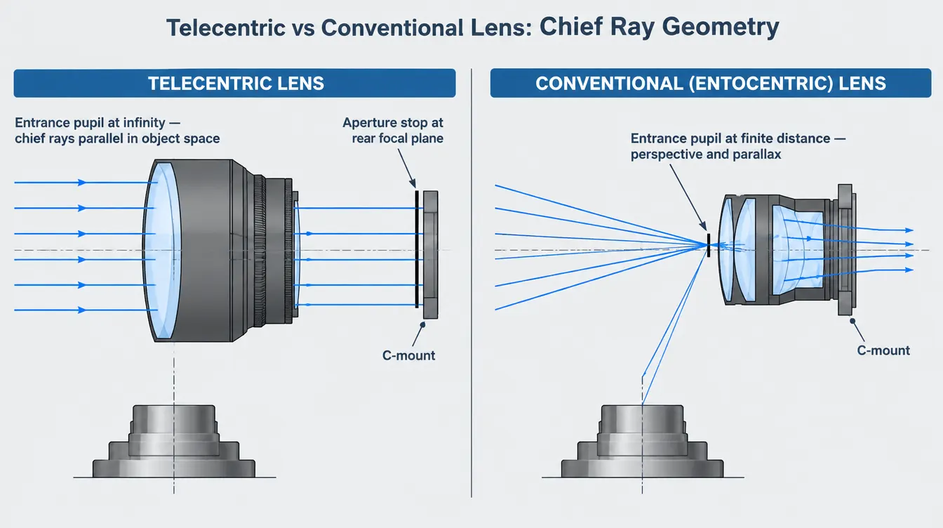
A telecentric lens keeps image magnification essentially constant while the object moves along the optical axis, within a defined telecentric range. A conventional imaging lens does not: as the object moves closer or farther, its image grows or shrinks. That single difference decides most selection questions. If the measurement is the dimension — edge-to-edge width, hole diameter, pin pitch, thread profile — and the part height, fixturing or presentation varies, a telecentric lens removes an error source that no software calibration can fully recover. If the task is presence/absence, code reading, surface defect detection or any inspection where absolute size is not the acceptance criterion, a conventional lens is usually the better engineering and commercial choice.
What makes a lens telecentric?
In an object-space telecentric lens, the aperture stop sits at the rear focal plane of the optical system. This places the entrance pupil at infinity, so the chief ray from every field point travels parallel to the optical axis in object space. The lens only accepts rays that arrive almost parallel to the axis, and it sees every point of the field from the same direction.
A conventional lens — properly called entocentric — has its entrance pupil at a finite distance. Chief rays converge toward that pupil, so field points are viewed from different angles. This is exactly how human vision and normal photography work, and it produces perspective: near objects look larger, and the lens sees partway into the sidewalls of a bore or the flanks of a stepped part. Perspective is useful for interpretation and harmful for measurement.
Why does a conventional lens change the measured size of a part?
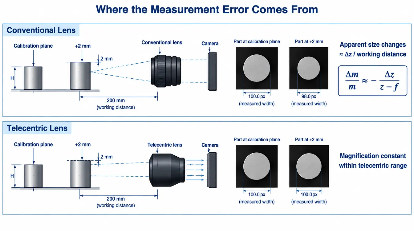
For a thin-lens approximation, transverse magnification is m = f / (z − f), where z is the object distance and f the focal length. Differentiating gives a useful field rule:
- Δm / m ≈ − Δz / (z − f)
- In practice, the relative sizing error is roughly the axial displacement divided by the working distance.
A part presented 2 mm higher than the calibration plane, viewed at a 200 mm working distance, shifts apparent size by about 1%. On a 20 mm feature that is roughly 0.2 mm — usually far larger than the camera’s pixel-level resolution, and completely invisible in the image. The error scales with feature size, so it is the large dimensions in the field that fail first.
The same geometry produces parallax: a hole away from the image centre is viewed obliquely, so the bore wall is imaged and the apparent diameter depends on the hole’s position in the field and on part thickness. A telecentric lens views all field points along parallel chief rays, so within its telecentric range the top edge and the bottom edge of a through-hole project onto the same image coordinates.
Telecentric vs conventional lens: side-by-side
| Property | Telecentric lens | Conventional (entocentric) lens |
|---|---|---|
| Magnification vs object distance | Essentially constant inside the telecentric range | Varies continuously with object distance |
| Perspective / parallax | Suppressed; no visible sidewalls on through-features | Present; grows with field position and part height |
| Field of view | Fixed, and limited by the front element diameter | Adjustable by working distance; can be very large |
| Front element size | Must exceed the field of view diagonal | Independent of field of view |
| Working distance | Fixed by design; refocusing range is narrow | Flexible over a wide range |
| Distortion specification | Typically specified very low, as a metrology parameter | Higher; usually corrected by camera calibration |
| Telecentricity specification | Stated as a residual chief-ray angle, a fraction of a degree in most designs | Not applicable |
| Illumination pairing | Works with collimated or telecentric backlight for edge measurement | Works with diffuse, dome, dark-field, bar and ring lighting |
| Size, mass, mounting load | Large and heavy for wide fields; needs rigid mounting | Compact; C-mount bodies are easy to fixture |
| Relative cost | High, and rising steeply with field of view | Low to moderate |
| Best suited to | Dimensional gauging, thickness, hole and thread metrology, high-aspect features | Presence/absence, OCR, code reading, surface and cosmetic inspection, large-area imaging |
Object-space, image-space or bi-telecentric?
Telecentricity can be designed into either conjugate, and the two solve different problems.
- Object-space telecentric — chief rays parallel in object space. This is the property that stabilises magnification against object movement, and it is the one dimensional measurement depends on.
- Image-space telecentric — chief rays arrive at the sensor near-normal across the field. This matters for sensor angular response and pixel shading, and it matters a great deal when an interference filter sits in front of the sensor, because the passband of an interference filter shifts toward shorter wavelengths as the angle of incidence increases. Non-uniform incidence angles across the field translate into non-uniform spectral response.
- Bi-telecentric (double telecentric) — telecentric in both spaces. It reduces residual magnification sensitivity, tolerates sensor-plane positioning error better, and behaves more predictably on thick parts, at the cost of a longer, larger and more expensive assembly.
Specifying “telecentric” without naming the conjugate is one of the more common sources of mismatch between what an integrator expects and what arrives.
What a telecentric lens costs you
The constraint that dominates the bill of materials is geometric: because the lens must accept axis-parallel chief rays from every field point, the front element has to be at least as large as the field of view. A 100 mm field needs a front element larger than 100 mm. Glass volume, mass, mounting stiffness and price all scale with that diameter, which is why wide-field telecentric optics become disproportionately expensive rather than linearly expensive.
Three further trade-offs are worth stating explicitly:
- Magnification is fixed, so field of view is fixed. Field of view equals sensor dimension divided by magnification. Changing the inspected part size usually means changing the lens, not moving the camera.
- Telecentric range is not depth of field. Inside the telecentric range the measured size is stable; that does not mean the image is sharp. Blur still grows away from best focus, and edge-finding precision degrades with it. Both parameters have to be checked against the part’s height variation.
- Mechanical alignment becomes a metrology error. Because the lens is long, heavy and referenced to a fixed working distance, tilt, sag and thermal drift in the mount move the measurement. A telecentric lens on a flexible bracket can be less accurate than a well-calibrated conventional lens on a rigid one.
When is a conventional lens the better choice?
A conventional lens is the correct answer more often than lens marketing suggests. It is preferable when the field of view is larger than a telecentric front element could reasonably cover; when the part is essentially flat and always presented at the same plane, so the residual perspective error falls below the measurement tolerance; when the task is classification rather than gauging; when working distance has to change between product variants; and when the optical budget is better spent on illumination, which usually contributes more to defect detection performance than lens type does.
It is also the practical choice when calibration can absorb the error. A camera calibrated with a target at the measurement plane can correct distortion and scale for objects in that plane. What calibration cannot correct is an unknown, varying object height — that is the residual case that justifies telecentric optics.
How to specify the lens once the type is decided
These parameters should be settled together, because they interact:
- Sensor format and pixel pitch — the lens image circle must cover the sensor diagonal, and the resolution has to be meaningful at that pixel pitch rather than at a nominal value.
- Required field of view and magnification — field of view equals sensor size divided by magnification; confirm both axes, not only the diagonal.
- Working distance and available mechanical envelope — including clearance for the illumination and for part transport.
- Part height variation and required telecentric range — state the total axial variation the system must tolerate, including fixture tolerance.
- Residual telecentricity and distortion limits — these belong in the specification as numbers with test conditions, not as adjectives.
- Illumination geometry — a telecentric lens paired with a diffuse backlight discards much of its edge-definition advantage; collimated or telecentric backlighting is what makes silhouette measurement repeatable.
- Spectral conditions — the illumination wavelength band, any bandpass or IR-cut filter in the path, its position in the optical train and the angle of incidence range it will actually see.
- Acceptance criteria — measurement uncertainty, repeatability and the gauge study the system must pass, defined before the optics are ordered.
Common mistakes
- Treating telecentricity as a substitute for calibration. It removes a specific error term; it does not deliver a calibrated measurement system by itself.
- Assuming a telecentric lens gives greater depth of field. Telecentric range and depth of field are separate specifications and are often different numbers.
- Selecting on field of view alone, then discovering the front element will not fit into the machine or the stated working distance.
- Placing an interference filter in a strongly convergent part of the optical path, then investigating a “coating problem” that is actually an angle-of-incidence effect.
- Comparing a telecentric quotation against a conventional lens quotation without including the illumination, mounting and calibration effort each option requires.
- Specifying “high accuracy” instead of a tolerance with a stated measurement condition, which leaves the supplier unable to select or verify anything.
FAQ
Can a conventional lens be used for dimensional measurement?
Yes, when the object plane is stable and the system is calibrated at that plane. The limitation appears when part height, fixture position or product variant changes the object distance, because the resulting scale error is indistinguishable from a real dimensional change in the image.
Does a telecentric lens eliminate distortion?
No. Telecentricity and distortion are independent properties. Telecentric lenses are usually designed and specified for low distortion because they are built for metrology, but the distortion figure still has to be read from the datasheet and verified under the intended conditions.
What is the difference between telecentric range and depth of field?
Telecentric range is the axial interval over which magnification stays within a stated tolerance. Depth of field is the axial interval over which the image stays acceptably sharp. A part can sit inside the telecentric range and still be too blurred for reliable edge detection.
Why does a telecentric lens need a large front element?
Because it accepts only chief rays that are parallel to the optical axis, light from the edge of the field must enter the front element directly opposite that point. The front aperture therefore has to be at least as large as the field of view, which sets the size, mass and cost of the lens.
Does an interference filter behave differently behind a telecentric lens?
Yes. In a near-collimated, image-space telecentric path, all rays strike the filter at similar angles, so the passband stays consistent across the field. In a convergent path the angle of incidence varies with field position, and the centre wavelength shifts accordingly. Filter position and the angle of incidence range should be defined together with the filter specification.
Specifying the optics for a measurement system
Lens architecture determines what the system can measure; the individual components — precision lenses, windows, apertures, prisms, mirrors and the bandpass or IR-cut filters in the path — determine whether it holds that performance in production. For component-level items in a vision or metrology assembly, send the drawing, optical specification or sample to GIAI together with the wavelength range, substrate, dimensions and geometry, coating requirements, angle of incidence, inspection criteria and expected quantity, and the request will be reviewed against manufacturing feasibility before any commitment is made.