
- A split ratio only means something when wavelength range, angle of incidence and polarization state are written next to it.
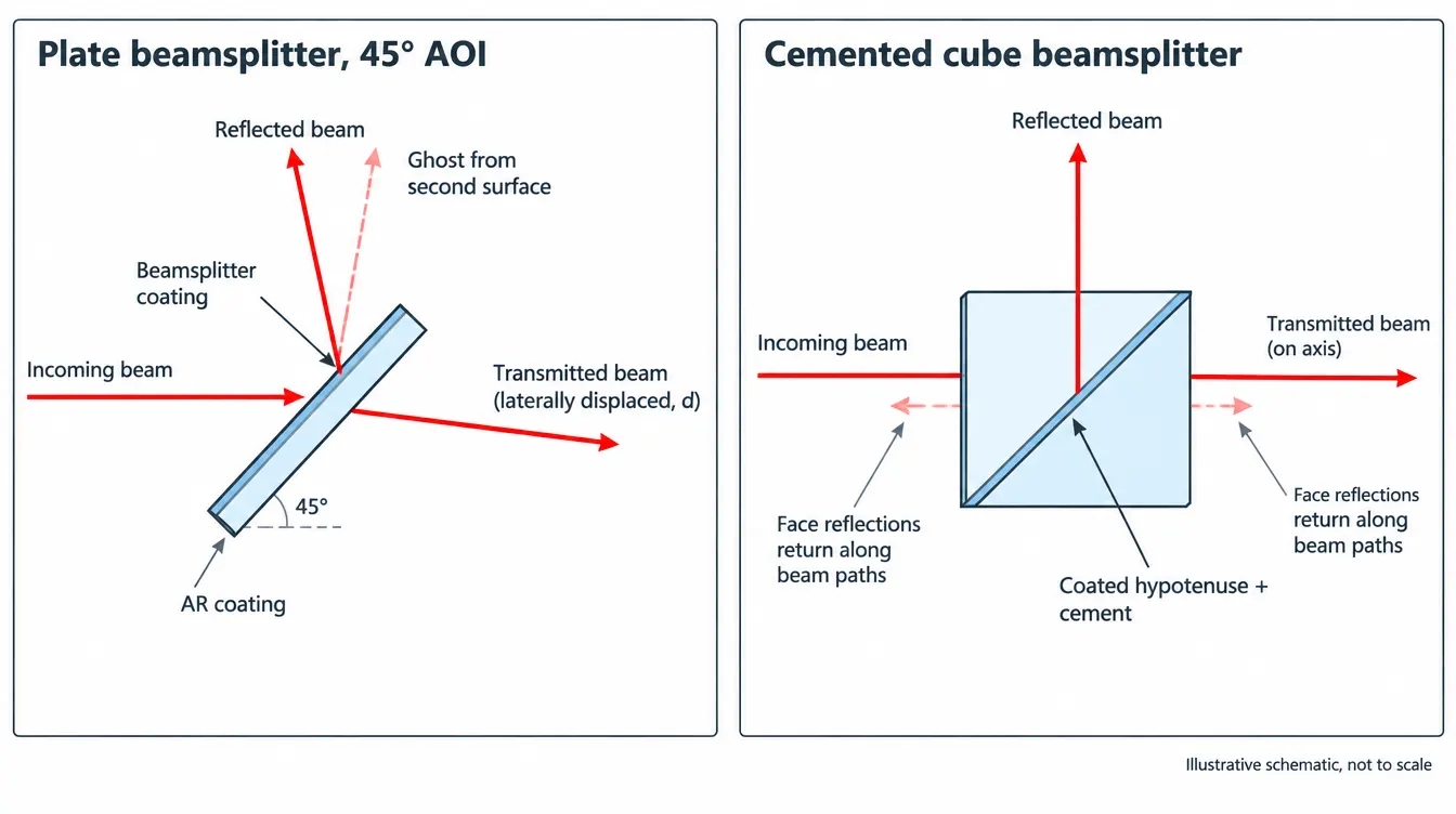
- Plates shift the transmitted beam and separate the ghost; cubes stay on axis but add glass path and a cemented interface.
- Non-polarizing, broadband and low-absorption are competing coating targets. A design that maximizes one gives ground on another.
- Ask for spectral data measured on the part, or on a witness of the same run, at your AOI and polarization.
- ISO 9001 certifies a management system. It does not certify the optical performance of a beamsplitter.
A beamsplitter manufacturer converts a split ratio, wavelength range, angle of incidence and polarization state into a coated plate, cube or dichroic component. Qualifying one comes down to three checks: the coating design covers your operating conditions, the fabrication holds wavefront and beam deviation, and the spectral data are measured at your AOI and polarization.
This page covers what a beamsplitter supplier needs from you, which construction and coating choices carry real consequences, and what evidence separates a capable source from a catalog reseller. Stock parts work when your conditions match the catalog conditions. Custom work starts when they do not.
What does a beamsplitter manufacturer actually control?
A manufacturer controls four things: the substrate and its geometry, the thin-film coating that sets the split, the assembly method for cubes, and the measurement that proves the result. Each one maps to a line on the drawing. A gap in any of the four shows up as an unexplained difference between the quoted curve and the delivered part.
- Substrate fabrication. Material grade, thickness, parallelism or wedge, surface figure, surface quality and edge geometry. For cubes, the 90° and 45° prism angles.
- Coating. The splitting coating on one surface and, for plates, an anti-reflection coating on the other. Both are designed for one AOI and one polarization condition.
- Assembly. Cementing or optical contacting of the two prisms in a cube, which sets transmitted beam deviation and limits power handling.
- Verification. Spectral measurement at angle, wavefront measurement, beam deviation measurement and visual inspection against the agreed criteria.
Suppliers of beamsplitter components differ mainly in how many of these steps they run in-house and how they document the last one.
Which beamsplitter construction should you ask for?
Choose the construction by what the beam path can tolerate: lateral shift, extra glass, a cemented interface or a fragile membrane. The split ratio rarely decides between plate and cube, because both can carry the same coating function. Geometry, power and ghost behavior decide it.
| Construction | Transmitted beam | Ghost path | Main limitation |
|---|---|---|---|
| Plate | Shifted laterally | Offset, parallel to reflected beam | Astigmatism in converging beams |
| Cube (cemented) | On axis | Back along the beam paths | Cement absorption and power handling |
| Pellicle | Negligible shift | Overlaps main beam | Fragile, vibration sensitive |
| Wedged plate | Shifted and deviated | Angularly separated | Dispersion from the wedge |
A tilted plate displaces the transmitted beam by d = t·sinθ·[1 − cosθ/√(n² − sin²θ)]. For a 1 mm thick plate with n = 1.5168 at 45° AOI, the shift is 0.33 mm, and it scales linearly with thickness. This is a calculated value, not measured product data.
The second surface of a plate creates the ghost. On an uncoated surface with n = 1.5168 at 45°, the calculated Fresnel reflectance is 9.6% for s-polarization and 0.92% for p-polarization. That gap is why the back-surface AR coating has to be specified for the same AOI and polarization as the splitting coating, and why a ghost that is invisible in p can be obvious in s.

A cube places the coating between two right-angle prisms, so both arms travel through the same glass path and the transmitted beam stays on axis at normal incidence. The cost is glass in the beam and a bonded interface. In a converging beam that glass adds spherical aberration and longitudinal chromatic shift, while a tilted plate adds astigmatism instead. Related prism geometries are grouped under optical prisms.
How should the split ratio and coating be specified?
State the split ratio together with the wavelength range, the AOI, the polarization state and the tolerance. A ratio written without those four conditions cannot be designed, measured or rejected. An example of a complete line is: R/T = 50/50 ± 5% absolute, average over 450–650 nm, 45° AOI, unpolarized light.
| Parameter | What to state | Why it matters |
|---|---|---|
| Split ratio | R and T targets with tolerance | R:T ratio differs from absolute R and T when the coating absorbs |
| Wavelength | Band limits or laser line | Sets coating type and layer design |
| AOI | Nominal angle and cone or field range | Spectral features shift to shorter wavelength as AOI increases |
| Polarization | s, p, unpolarized, or allowed s–p difference | s and p reflectance differ at oblique incidence |
| Second surface | AR reflectance limit at the same AOI | Sets ghost intensity |
| Wavefront | Transmitted and reflected error, test wavelength | Two arms have different error sources |
| Beam deviation | Transmitted and reflected limits | Driven by wedge in plates, prism angles in cubes |
| Laser exposure | Wavelength, pulse duration, repetition rate, beam diameter | A damage threshold has no meaning without them |
Three coating families cover the common requests, and each is a different design problem.
- Non-polarizing. The design keeps s and p reflectance close over a defined band and angle range. Metal-dielectric coatings achieve this over wide bands but absorb part of the light, so R + T falls below 100%. All-dielectric designs have negligible absorption and hold the s–p match over a narrower band.
- Polarizing. The coating transmits p and reflects s. In a MacNeille-type cube the transmitted arm carries the higher extinction ratio, because residual p reflectance contaminates the reflected arm. The specification should name the arm, the band and the acceptance angle.
- Dichroic. The split is by wavelength. The edge moves to shorter wavelength as AOI increases, and the s and p edges separate at oblique incidence, so edge position must be tied to both conditions.

Background on angle and polarization behavior in thin-film designs is collected in the filters and coatings resources.
What trade-offs does the manufacturer have to resolve?
Every beamsplitter design gives up something to meet its primary target. A supplier who agrees to every requirement without naming a compromise has either not run the design or is quoting a stock part. The useful conversation is about which parameter can relax.
- Bandwidth against ratio flatness. Widening the band of an all-dielectric splitter increases ripple in R and T. Metal-dielectric coatings flatten the ratio and pay for it in absorption.
- Polarization neutrality against efficiency. Tightening the allowed s–p difference narrows the usable band or pushes the design toward absorbing layers.
- Extinction against angular acceptance. Thin-film polarizing cubes reach high extinction only within a limited cone around the design angle.
- Plate thickness against displacement. A thicker plate resists coating stress and holds flatness, and it increases both beam shift and ghost separation. Larger separation helps when the ghost can be blocked by an aperture and hurts when the detector covers both beams.
- Wedge against chromatic behavior. A wedge steers the ghost out of the path and removes etalon fringes with coherent sources. It also deviates and disperses the transmitted beam.
- Cement against power. A cemented cube is mechanically simple to mount. The cement layer absorbs in the UV and sets the power limit, which is why optically contacted or air-spaced designs exist.
Surface figure matters differently in the two arms. A figure error of height h on the splitting surface produces a reflected wavefront error of 2h·cosθ, which is 1.41h at 45°. The transmitted arm sees that error scaled by (n − 1) effects through both surfaces and is dominated by substrate homogeneity and parallelism. Flatness should therefore be specified after coating, because coating stress can bend a thin plate.
How do you verify that a supplier can deliver?
Ask for measured data taken under your conditions and ask how it was taken. A design curve shows intent. A measured curve at the stated AOI and polarization, on the part or on a witness from the same coating run, shows the result.
- Spectral data at angle. Measuring at 45° requires an angled sample stage and a polarizer in the instrument beam. An unpolarized value should be reported as the mean of separate s and p measurements, since a spectrophotometer beam is itself partially polarized.
- Part or witness. Cube coatings sit inside the glass, so the meaningful measurement is on the assembled cube. Ask which was measured.
- Wavefront and deviation. Interferometry for transmitted and reflected wavefront, and an autocollimator or goniometer for beam deviation and prism angles.
- Coating durability. Adhesion, abrasion and humidity tests referenced to a named standard such as ISO 9211-3, agreed before production.
- Process ownership. Which of polishing, coating, cementing and measurement are done in-house, and which are subcontracted.
- Quality system. An ISO 9001 certificate covers the management system of a named legal entity and site. It does not state the performance of any optical part, so check holder, scope and validity dates.
GIAI lists beamsplitters among its manufactured component families and reviews each custom project against the drawing, sample, optical requirements, substrate, geometry, coating conditions and inspection criteria before defining the manufacturing route. The public scope of fabrication, coating and inspection steps is described under manufacturing capabilities, the way acceptance criteria are set is covered in quality assurance, and certificate details are on the certifications and compliance page.
Which specification mistakes cause rejected parts?
Most rejected beamsplitters met the drawing and failed the application, because the drawing left out a condition. Five omissions account for the bulk of these disputes.
- “50/50” with no conditions. The supplier picks a wavelength, an angle and unpolarized light. A linearly polarized laser then sees a different ratio.
- Collimated specification, converging beam. A cone of rays spans a range of AOI, which broadens edges and changes the average ratio. State the cone half angle.
- Clear aperture taken from beam diameter. At 45° a round beam of diameter D covers an ellipse 1.41D long on the surface. Size the aperture along the tilt axis from that figure, plus alignment margin.
- No ghost requirement. Without a second-surface reflectance limit at the working AOI and polarization, the AR coating is a normal-incidence default.
- Unlabeled orientation. The splitting coating should face the source when the reflected arm must avoid the substrate. Ask for an edge mark identifying the coated side.
For a first project, sending a sample or an existing part together with the drawing shortens the review, since the supplier can measure what currently works. The steps from requirement review to inspection are outlined in the custom optics process.
Frequently asked questions
What is the difference between a plate and a cube beamsplitter?
A plate beamsplitter is a single coated window tilted in the beam; it is light, has no cement, and shifts the transmitted beam sideways. A cube beamsplitter is two right-angle prisms joined at a coated hypotenuse; it keeps the transmitted beam on axis and mounts easily, but adds glass path and a cemented interface that can limit power handling and UV use.
What does a 50/50 beamsplitter mean?
A 50/50 beamsplitter reflects half and transmits half of the incident power under one stated set of conditions: wavelength range, angle of incidence and polarization. Outside those conditions the ratio moves. With an absorbing metal-dielectric coating the two outputs can be equal while each is below 50% of the input, so the specification should say whether the ratio refers to R:T or to absolute R and T.
Are beamsplitters polarization dependent?
Beamsplitters used at oblique incidence are polarization dependent because s- and p-polarized light have different reflectance at any tilted interface. Non-polarizing designs reduce the difference over a defined band and angle range but do not remove it. A split ratio is only meaningful when the polarization state, s, p or unpolarized, is stated with it.
What is the difference between a dichroic mirror and a beamsplitter?
A dichroic mirror is a beamsplitter that divides light by wavelength: it reflects one spectral band and transmits another. A neutral beamsplitter divides power by a fixed ratio across its band. Dichroic specifications therefore add an edge wavelength, edge steepness, and reflection and transmission bands, all stated at the working angle of incidence and polarization.
Can a beamsplitter be used at an angle other than 45°?
A beamsplitter can be designed for any angle of incidence the coating design supports, and 45° is a convention set by 90° beam folding. A coating designed for 45° will not hold its split ratio at another angle, because layer phase thickness and s and p reflectance both depend on angle. Lower angles reduce the s and p difference, which helps non-polarizing and dichroic designs.
References
- ISO 10110, Optics and photonics — Preparation of drawings for optical elements and systems.
- ISO 9211, Optics and photonics — Optical coatings (including Part 3: Environmental durability).
- ISO 21254, Lasers and laser-related equipment — Test methods for laser-induced damage threshold.
- H. A. Macleod, Thin-Film Optical Filters, CRC Press.
- E. Hecht, Optics, Pearson (Fresnel equations and polarization on reflection).
To have a beamsplitter requirement reviewed, send GIAI the drawing, optical specification or sample together with the wavelength range, split ratio and tolerance, AOI, polarization state, substrate, dimensions and clear aperture, second-surface coating requirement, inspection criteria and expected quantity through the project contact page.