
Technical Resources
F-Theta Lens Focal Length vs Scan Field
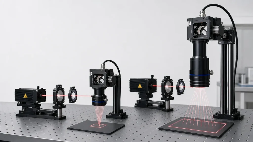
The relationship behind F theta lens focal length vs scan field is straightforward at first order: for an ideal F-theta mapping, the displacement of the focused spot is approximately proportional to effective focal length and optical scan angle. A longer focal length therefore produces a larger spot displacement for the same beam-deflection angle.
This distinction matters when comparing F-theta lenses with apparently similar specifications. A 160 mm lens does not automatically provide a particular marking field, and two 160 mm lenses may legitimately have different rated fields.
The Basic F-Theta Relationship
An F-theta lens is designed for an angularly scanned beam. The galvanometer or other scanner changes the direction of the incoming beam, and the lens converts that angular change into displacement of the focused spot across the work plane.
For an ideal one-dimensional F-theta mapping:
where:
- y = spot displacement from the field center
- f = effective focal length, or EFL
- θ = optical scan angle from the optical axis, expressed in radians
The use of radians is essential. To convert degrees to radians:
If the scan is symmetric from −θ to +θ, the first-order full span along that scan direction is:
This equation explains why longer focal lengths are commonly associated with larger scan fields. It is a geometric starting point, however, not a complete lens specification.
F-Theta Lens Focal Length vs Scan Field: A Worked Comparison
Consider several effective focal lengths while holding the optical half-angle constant. The following values use the ideal one-dimensional F-theta relationship and do not represent specifications for any particular commercial lens.
| Effective Focal Length | Full Span at ±10° | Full Span at ±20° |
|---|---|---|
| 100 mm | 34.9 mm | 69.8 mm |
| 160 mm | 55.9 mm | 111.7 mm |
| 254 mm | 88.7 mm | 177.3 mm |
Theoretical values calculated from W = 2fθ, with θ expressed in radians. They are one-dimensional geometric spans, not guaranteed usable processing fields.
The proportional trend is clear. At the same ±20° optical scan angle, changing EFL from 100 mm to 160 mm increases the theoretical span by a factor of 1.6. Increasing it from 100 mm to 254 mm increases the span by a factor of 2.54.
That does not mean that every 254 mm F-theta lens provides 177.3 mm of usable field. The optical design may permit a different maximum field angle, and the scanner or aperture may become the limiting element first.
Calculating Focal Length From a Required Field
The same relationship can be reversed during preliminary system design.
For a required symmetric one-dimensional span W:
Suppose the system requires approximately 100 mm of full scan span and the available optical half-angle is ±20°.
First convert 20° to radians:
Then:
A focal length near this value is therefore a reasonable geometric starting point. It is not yet a lens selection. The next step is to identify an actual F-theta design that supports the required field with acceptable spot quality, clear aperture, working distance, telecentricity and scanner geometry.
Why Focal Length Does Not Uniquely Determine Scan Field
The equation y = fθ is useful precisely because it is simple. Real scanning systems are not. Several factors determine how much of the calculated field can actually be used.
1. The lens has a limited designed scan angle
An F-theta lens is corrected over a specified angular field. Increasing the galvo command beyond that range does not create unlimited usable field. At larger angles, the beam may encounter increasing aberration, field curvature, distortion or mechanical clipping.
For this reason, comparing focal lengths without comparing the specified scan angle can be misleading. A shorter lens designed for a larger angular field can sometimes approach the field of a longer lens designed for a smaller angle.
2. “Scan field” is not defined identically on every datasheet
This is one of the most important specification checks.
A datasheet may describe:
- a square working field such as 100 × 100 mm,
- a rectangular X × Y scan area,
- a one-axis scan length,
- a field diameter, or
- a diagonal scan length associated with a square field.
These quantities are not interchangeable.
3. Scanner geometry changes the usable field
A two-axis galvanometer normally uses two mirrors at different physical positions. The X and Y beams therefore do not originate from exactly the same point. Mirror separation, scanner-to-lens distance and entrance-pupil position influence beam walk through the lens.
If the scanner is positioned differently from the geometry assumed in the optical design, the beam may approach an aperture edge sooner than expected. The consequence can be reduced usable field, increased vignetting or different edge performance.
4. Beam diameter consumes aperture
The laser beam is not an infinitesimal ray. A finite beam must pass through the scanner mirrors and lens aperture at every scan position.
Increasing input beam diameter can reduce the diffraction-related focused spot, but the larger beam requires more clear aperture. At large scan angles, beam walk makes this requirement more severe.
This creates an important coupling between F-theta lens spot size vs beam diameter and scan field: increasing the beam diameter to recover a smaller spot can reduce the available aperture margin at the field edges.
Mechanical Mirror Angle Is Not Automatically Optical Scan Angle
A common calculation error is to place a galvanometer’s mechanical rotation directly into the F-theta equation.
For a simple rotating plane mirror, a mechanical mirror rotation of α changes the reflected beam direction by approximately 2α. Therefore, a mirror rotating by ±10° can correspond to approximately ±20° of optical beam deflection in that simple geometry.
Scanner specifications are not always presented using the same convention, however. Some documentation reports mechanical mirror angle, while other documentation reports optical deflection angle or a system-level field angle.
Before performing an F-theta calculation, establish exactly what the specified angle represents.
Larger Scan Field Comes With Optical Trade-Offs
If every other parameter could remain fixed, selecting a longer focal length would be an easy way to enlarge the field. In practice, changing focal length also changes several other parts of the optical system.
Focused spot size
For a collimated Gaussian-like beam, the diffraction-related focused spot diameter follows approximately:
where λ is wavelength, D is the input beam diameter and M² represents beam quality.
The important engineering trend is that, with wavelength and beam diameter unchanged, spot size increases approximately with focal length. A lens selected for a substantially larger field may therefore produce a larger diffraction-limited spot.
This is why scan field and processing resolution cannot normally be optimized independently.
Beam diameter and scanner aperture
One way to reduce the spot-size penalty of a longer focal length is to increase the collimated input beam diameter. That approach requires larger scanner mirrors and sufficient lens aperture throughout the complete scan.
A beam that fits comfortably on axis may clip when the scanner approaches a field corner. Vignetting can reduce transmitted power and distort the focused intensity distribution.
Working distance
Longer-EFL F-theta lenses often provide greater mechanical clearance, but working distance is not the same quantity as effective focal length.
EFL is referenced to the principal planes of the optical system. Working distance is referenced to a defined physical surface of the lens or housing. Back focal length, flange focal distance and working distance may all differ from EFL.
Use the mechanical drawing rather than focal length alone when establishing the machine envelope.
Edge-of-field performance
Increasing field angle places greater demands on off-axis aberration correction. Residual astigmatism, coma, field curvature and F-theta distortion may vary with field position.
A lens can therefore satisfy the required geometric field while still failing the application’s spot-size or focus-uniformity requirement at the edges and corners.
F-Theta Distortion and Scan Field Are Different Specifications
The ideal F-theta relationship is linear:
A real lens has some residual departure from that relationship. This is commonly described as F-theta distortion.
Geometric calibration can often compensate repeatable position errors by changing scanner commands. It cannot compensate for an optical spot that has become enlarged because of defocus, aberration or clipping.
It is therefore useful to separate two questions:
- Does the focused spot arrive at the correct coordinate?
- Is the spot optically acceptable at that coordinate?
Scanner calibration primarily addresses the first question. Lens design and system integration determine the second.
What Happens in a Two-Axis Scan Field?
The simple y = fθ equation describes an idealized angular mapping and is easiest to understand in one dimension. A real XY galvo system has two sequential mirrors, finite mirror separation and two angular coordinates.
For preliminary sizing, engineers can use the F-theta relationship to estimate the required EFL and angular range. For the final rectangular or square work field, however, use the actual lens data and scanner geometry rather than assuming that the one-dimensional maximum displacement can be reached simultaneously in both X and Y.
This is particularly important at field corners, where beam walk, aperture requirements and combined scan angle can be greater than along one axis.
Does a Telecentric F-Theta Lens Change the Relationship?
A telecentric F-theta lens still performs scan mapping, but it is additionally designed to keep the output chief ray close to normal to the work surface throughout the specified field.
This matters when beam incidence angle affects the process, such as some drilling, precision structuring and metrology configurations.
Telecentricity does not remove the focal-length-versus-field trade-off. It adds another design constraint and generally requires substantial optical aperture because off-axis beams must be delivered across the field while maintaining the required chief-ray geometry.
When comparing an F-theta lens vs standard focusing lens, remember that flat-field correction, F-theta mapping and telecentricity are separate optical properties. One does not automatically guarantee the others.
How to Select F-Theta Focal Length From a Required Scan Field
A reliable selection process works from the system outward rather than choosing a familiar focal length first.
- Define the operating wavelength. The optical prescription, coating and effective focal length are wavelength-dependent.
- Define the required usable field. State whether the requirement is X × Y, diameter, diagonal or one-axis scan length.
- Determine the available optical scan angle. Confirm whether the scanner specification uses mechanical or optical angle.
- Estimate EFL from the F-theta relationship. Use f ≈ W/(2θ) as an initial calculation when appropriate.
- Check the required focused spot. Evaluate wavelength, beam diameter, M² and field-dependent aberrations.
- Check scanner and lens apertures. Include beam walk at maximum field position rather than evaluating only the on-axis beam.
- Confirm entrance-pupil and mirror geometry. Use the lens’s intended scanner spacing wherever possible.
- Verify edge and corner performance. Review spot size, field curvature, distortion, vignetting and incidence angle across the complete usable area.
- Confirm working distance mechanically. Do not substitute EFL for the specified working distance.
- Plan system calibration. Residual coordinate distortion should be treated separately from optical focus quality.
Common Mistakes When Comparing Focal Length and Scan Field
| Mistake | Why It Causes Problems |
|---|---|
| Choosing a lens from focal length alone | Maximum scan angle and usable aperture can differ substantially between designs with the same EFL. |
| Putting degrees directly into y = fθ | The F-theta equation requires θ in radians. |
| Confusing mechanical and optical scan angle | A reflecting scanner mirror changes beam direction differently from its mechanical rotation angle. |
| Assuming scan length means square-field width | Datasheet definitions vary; scan length may instead describe a diagonal, diameter or another field dimension. |
| Ignoring beam diameter | A large beam may clip at high scan angles even when it passes through the lens on axis. |
| Assuming EFL equals working distance | The two quantities use different reference planes. |
| Using software calibration to compensate poor focus | Calibration can correct coordinate mapping but cannot remove optical aberration, clipping or defocus. |
Conclusion
The central relationship between F-theta lens focal length and scan field is simple: at a fixed optical scan angle, a longer effective focal length produces greater spot displacement and therefore a larger theoretical field.
The usable processing field is more complicated. Focal length must be evaluated together with the lens’s designed scan angle, beam diameter, scanner aperture, mirror spacing, entrance-pupil position, spot requirement, field curvature, distortion, working distance and telecentricity.
For preliminary design, use y ≈ fθ to establish the geometry. For final optical selection, use the specified field performance of the complete lens-and-scanner configuration. That distinction prevents a calculated scan field from being mistaken for a guaranteed usable work area.
Frequently Asked Questions
Does doubling F-theta focal length double the scan field?
Approximately yes if the available optical scan angle remains the same. Under the ideal F-theta relationship, spot displacement is y = fθ, so doubling effective focal length doubles theoretical displacement at a given angle. In a real system, however, the longer lens may have a different maximum designed scan angle, entrance-pupil position or aperture requirement. The scanner mirrors may also limit the usable beam angle. Therefore, the proportional relationship is useful for first-order comparison but does not mean every lens with twice the focal length provides exactly twice the specified working field.
Can I calculate F-theta focal length from the required scan field?
Yes, as a preliminary estimate. For a symmetric one-dimensional field of full width W and an available optical half-angle θ, the first-order relationship is f ≈ W/(2θ), with θ in radians. The result gives an approximate EFL around which to search for a suitable lens. Final selection still requires checking the actual lens field definition, scanner geometry, input beam diameter, clear aperture, spot size, working distance and edge performance. The calculated EFL should therefore be treated as a system-design starting point rather than a finished optical specification.
Why can two F-theta lenses with the same focal length have different scan fields?
Because effective focal length is only one variable controlling the field. Two lenses with identical EFL can be designed for different maximum scan angles, beam diameters, entrance-pupil positions, scanner geometries and levels of acceptable aberration or vignetting. Their datasheets may also use different definitions of scan field. One might specify an X × Y working area while another reports a scan length or diagonal. Compare focal length together with maximum field angle, aperture conditions and the exact definition of the published field.
Does a longer F-theta focal length always mean a longer working distance?
No, although longer-EFL designs often have longer working distances. Effective focal length is an optical property referenced to the principal planes of the multi-element lens system, while working distance is measured from a defined physical surface or housing reference to the work plane. Lens prescription, element spacing and housing design influence the relationship between them. Two F-theta lenses with similar focal lengths can therefore have different working distances. Mechanical integration should always use the specified working distance and dimensional drawing rather than estimating clearance directly from EFL.
How should I choose between a shorter and longer F-theta focal length?
Choose the shortest focal length that satisfies the required usable field while meeting the rest of the optical and mechanical requirements. A shorter focal length generally helps achieve a smaller diffraction-related spot for a fixed wavelength and beam diameter, while a longer focal length provides more displacement for a given scan angle and often more mechanical clearance. The final choice should balance field size, spot size, beam diameter, scanner aperture, edge performance, working distance, telecentricity and process tolerance rather than optimizing focal length as an isolated number.
