
Technical Resources
Laser Line Filter vs Laser Cleanup Filter
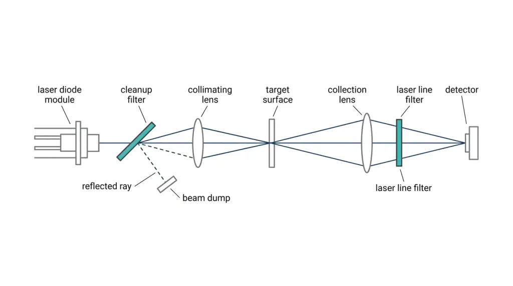
In most catalogs, “laser line filter” and “laser cleanup filter” describe the same physical object: a narrow dielectric bandpass filter centered on a laser wavelength. The real distinction in a laser line filter vs laser cleanup filter comparison is not the coating, it is where the filter sits in the optical path and what it is being asked to reject. A cleanup filter sits at the source and removes the laser’s own spurious emission. A detection-side laser line filter sits in front of a sensor and removes everything that is not the laser, mostly ambient and solar background. Those two jobs pull the specification in opposite directions, and a part that is excellent at one can be useless at the other.
A note on terminology before going further: “laser line” here means the spectral line of the laser, not the projected stripe from a line-generator lens used in triangulation profiling.
Why the two terms get used interchangeably
Vendor naming is inconsistent and always has been. Semrock’s MaxLine parts are labeled laser-line clean-up filters. Omega and Edmund Optics both sell “laser line filters” and “laser clean-up filters” that overlap heavily in construction. Alluxa and Iridian describe the same class of coating as narrow bandpass.
The overlap is real because the coating design is genuinely the same family: a multi-cavity all-dielectric Fabry-Perot stack, typically Ta₂O₅/SiO₂ or Nb₂O₅/SiO₂, deposited by ion-beam sputtering or plasma-assisted magnetron sputtering onto fused silica or a low-expansion glass. More cavities produce steeper edges and a squarer passband at the cost of layer count, thickness, and yield.
What differs is the requirement set. So the useful question is not “which product name do I buy,” it is “which side of the system am I on, and what is my dominant noise source.”
What a laser cleanup filter actually removes
A laser is never spectrally clean. Depending on the source, the output contains:
- Amplified spontaneous emission (ASE) from diode and diode-pumped solid-state (DPSS) lasers, spread over tens of nanometers around the line
- Plasma and discharge lines from gas lasers such as HeNe and Ar-ion
- Residual pump and fundamental light, for example 808 nm pump and 1064 nm fundamental leaking from a 532 nm DPSS module
- Fiber fluorescence and Raman background generated in a delivery fiber
None of this matters until it reaches something that scatters or fluoresces. In Raman spectroscopy it matters enormously: ASE from a 785 nm diode lands directly on the fingerprint region, scatters elastically off the sample, and swamps a Raman signal that is many orders of magnitude weaker. In fluorescence instruments, spontaneous emission from the laser leaks straight through the dichroic into the emission band and appears as a false signal.
A cleanup filter is therefore specified for deep blocking very close to the line, with steep edges, high peak transmission, and enough laser damage threshold to survive sitting in the raw beam. Blocking of optical density (OD) 5 to 6 within roughly one to two percent of the laser wavelength is a common commercial performance level for hard-coated laser-line parts, though the exact edge steepness varies by design.
What a detection-side laser line filter actually removes
At the receiver, the laser is the signal and everything else is noise. The dominant contributor in outdoor or open-path systems is solar background. In a light detection and ranging (LiDAR) receiver, a machine vision system using structured illumination, or an active triangulation sensor, the filter’s job is to pass the return and reject broadband daylight across the detector’s entire spectral response.
Two consequences follow, and they are the source of most specification errors.
First, blocking range matters more than blocking depth near the line. A silicon detector responds from roughly 350 nm to 1100 nm. An InGaAs detector responds to about 1700 nm. If your filter is blocked only from 400 nm to 900 nm, sunlight beyond that range reaches the sensor unattenuated no matter how good the OD 6 number in the datasheet looks.
Second, the filter usually sits in a converging beam, not a collimated one. Receiver optics are fast because they need to collect photons, and a fast cone destroys the passband of a narrow filter. This is the single most expensive mistake in receive-path design.
Under shot-noise-limited background, signal-to-noise ratio scales as 1/√Δλ, where Δλ is the effective passband width. Halving the bandwidth improves SNR by about 1.4x, which is why LiDAR designers push toward 10 nm and narrower, and why they then run headfirst into the angle problem.
Laser line filter vs laser cleanup filter: side-by-side
| Parameter | Cleanup filter (source side) | Laser line filter (detector side) |
|---|---|---|
| Position | Immediately after the laser, before delivery optics | In front of the photodiode, APD, SPAD, or camera |
| Rejects | ASE, plasma lines, residual pump, fiber background | Sunlight, room light, other sources in the scene |
| Beam condition | Collimated, well-defined AOI | Often a fast cone, wide field of view |
| Bandwidth driver | Just wide enough to cover the laser’s wavelength spread | As narrow as the cone angle and source drift allow |
| Blocking priority | Very deep, very close to the line | Moderate depth, but across the full detector response |
| Peak transmission | Critical, it is your laser power | Critical, it is your return signal |
| Power handling | High. Laser damage threshold and thermal load matter | Low. Handles returns, not the outgoing beam |
| Dominant failure | Passband misses the actual laser wavelength | Passband blue-shifts and broadens in the cone |
The angle shift you cannot design around
Every dielectric bandpass filter blue-shifts with angle of incidence (AOI). The standard relation is:
λ(θ) = λ₀ · √(1 − (n₀/n_eff)² · sin²θ)
where λ₀ is the normal-incidence center wavelength (CWL), n₀ is the index of the incident medium, θ is the AOI, and n_eff is the effective index of the filter design. n_eff is not a material constant. It is a property of the specific coating stack, commonly in the range of about 1.45 to 2.1, with higher values giving less shift. Ask the supplier for the value of the actual design rather than assuming one.
The following table uses n_eff = 2.0 in air. Treat it as illustrative, not as a universal rule.
| AOI (collimated) | Fractional shift | Shift at 785 nm | Shift at 905 nm |
|---|---|---|---|
| 2° | 0.015% | 0.12 nm | 0.14 nm |
| 5° | 0.095% | 0.75 nm | 0.86 nm |
| 10° | 0.38% | 2.96 nm | 3.42 nm |
| 15° | 0.84% | 6.60 nm | 7.61 nm |
| 20° | 1.47% | 11.6 nm | 13.3 nm |
Two corrections apply in real systems. In a cone of light rather than a tilted collimated beam, only the chief ray is at the nominal angle. Andover’s practical guidance is to compute the shift for the marginal ray and divide by roughly two for full cone angles up to about 20 degrees. And at non-normal incidence the s and p polarization components shift differently, so the band both broadens and loses peak transmission for unpolarized light.
Work an example. An f/1.4 collection lens has a marginal ray half-angle of about 20 degrees. At 905 nm with n_eff = 2.0, the marginal ray sees roughly a 13 nm blue shift, and the cone-averaged center moves several nanometers while the effective passband widens well beyond its nominal FWHM. Specify a 10 nm filter for that position and you have built something that neither passes your signal efficiently nor rejects daylight as designed. The fixes are to relocate the filter into collimated or near-telecentric space, to slow the optics, or to buy a filter designed and centered for that specific cone.
Temperature, and the wavelength budget
Interference filters red-shift with increasing temperature because the layers expand and their indices change. Thermal coefficients are usually quoted in picometers per degree Celsius. Hard-coated filters generally land in the low single digits to low tens of pm/°C depending on coating materials and substrate; Alluxa quotes roughly 2 to 5 pm/°C for its hard-coated parts, and Iridian describes a broader industry range of about 1 to 20 pm/°C. Over a −20 °C to +80 °C automotive or outdoor range, a 10 pm/°C part drifts a full nanometer.
The source drifts too, usually much faster. A near-infrared Fabry-Perot laser diode shifts about 0.3 nm/K. A distributed feedback (DFB) diode is closer to 0.1 nm/K. Add unit-to-unit manufacturing tolerance of a few nanometers and aging, and the wavelength budget for an unstabilized diode can exceed 10 nm.
This is why narrow cleanup filters and unstabilized diodes are a bad pairing, and why filters with a squarer, deliberately wider passband exist specifically for diode sources. If you want a sub-nanometer cleanup filter, you need a wavelength-stabilized laser, typically volume Bragg grating locked or a temperature-controlled DFB.
The trade-off, stated plainly
Narrowing the FWHM buys background rejection and costs you almost everything else:
- Peak transmission falls, particularly below about 1 nm FWHM
- CWL manufacturing tolerance must tighten, which lowers yield and raises price
- Angular acceptance shrinks, since a given angle shift is now a large fraction of the band
- Thermal sensitivity becomes a system-level problem rather than a footnote
- Layer count and coating thickness rise, which tends to degrade transmitted wavefront error
Hard-coated narrow bandpass filters in the visible and near-infrared routinely reach 90% or better peak transmission at bandwidths of a few nanometers. Push into the sub-nanometer regime and both transmission and price move against you. When you are comparing narrow bandpass and laser line filters across suppliers, insist on measured spectra of the actual part, not the design curve.
Common specification mistakes
Blocking range shorter than the detector response. OD 6 from 400 to 900 nm in front of a silicon sensor that sees to 1100 nm leaves a wide open door for solar background. State the blocking range explicitly, tied to the detector.
A narrow cleanup filter in front of an unstabilized diode. Cold start at −10 °C, a Fabry-Perot diode 6 nm from its 25 °C wavelength, and a 3 nm filter means your output power collapses. Match the passband to the full wavelength budget, not the nominal datasheet line.
Mounting a cleanup filter perpendicular to a high-power beam. The filter rejects by reflection, not absorption. That reflected beam goes straight back into the laser cavity and can cause mode hopping and power instability, and it needs somewhere safe to land. Tilt one to three degrees and dump the reflection. Note the cost: at 5° AOI, a 785 nm filter with n_eff = 2.0 already shifts about 0.75 nm, which is significant for a narrow part. Tilt tuning is also a legitimate technique for pulling a filter onto a wavelength, provided the CWL tolerance is specified with a deliberate red-shift bias.
Forgetting the pump. A 532 nm cleanup filter in a DPSS module must block 808 nm and 1064 nm, not just the region adjacent to 532 nm.
Putting glass between the cleanup filter and the sample in Raman. Any lens or window downstream regenerates its own Raman and fluorescence background. Put the cleanup filter as late in the excitation path as the geometry allows.
Ignoring orientation on multi-component filters. For filters that combine an interference coating with an absorbing glass blocker, orientation is not arbitrary. The interference coating should generally face the incoming light so most of the energy is reflected before it reaches the absorber, which reduces both fluorescence and thermal load. Single-substrate all-dielectric parts are far more forgiving.
Datasheet parameters worth arguing about
CWL and its tolerance. FWHM and its tolerance. Minimum transmission at the laser line, not average transmission over the band. OD with an explicitly stated wavelength range, since OD = −log₁₀(T) and a number without a range is meaningless. AOI and cone half-angle the part is specified at. Temperature coefficient and rated operating range. Clear aperture. Surface quality per MIL-PRF-13830B scratch-dig or ISO 10110-7. Surface form and transmitted wavefront error in waves peak-to-valley at 633 nm, which matters whenever the beam is focused downstream. And for anything in the outgoing beam, laser damage threshold measured per ISO 21254, with the pulse duration, wavelength, and repetition rate stated. A damage threshold quoted without test conditions tells you nothing.
Suppliers such as GIAI Photonics catalog these as separate families of bandpass filters, narrow bandpass filters, and infrared filters precisely because the receive-side and source-side requirements diverge, and it is worth confirming which family a quoted part belongs to before comparing prices.
How to choose
- Identify the dominant noise source. If it originates inside your laser, you need a cleanup filter. If it originates in the scene, you need a receive-side laser line filter.
- Write down the full wavelength budget: source tolerance, source thermal drift, filter thermal drift, filter CWL tolerance. That sum sets your minimum FWHM.
- Determine the actual angular condition at the filter plane, in degrees, not in f-numbers alone.
- Define the blocking range from the detector’s response curve, not from the filter catalog.
- Only then optimize for peak transmission and price.
FAQ
Is a laser cleanup filter just a narrow bandpass filter?
Physically, usually yes: a multi-cavity dielectric bandpass centered on a laser wavelength. The difference is in the specification. A cleanup filter emphasizes very steep edges and deep blocking immediately adjacent to the line, plus laser damage threshold, because it sits in the raw beam. A general narrow bandpass filter may have neither.
Can I use the same part at the source and at the detector?
Sometimes, in a collimated bench setup with a stable laser. Rarely in a fielded instrument. The receive-side part typically needs a much wider blocking range and a passband designed for a converging cone, while the source-side part needs steeper edges near the line and higher power handling.
How do I choose FWHM for a cleanup filter?
Sum the laser’s wavelength tolerance, its thermal drift over your operating range, and the filter’s own CWL tolerance and thermal drift. The passband must cover that whole span with margin. For a wavelength-stabilized source this can be under 1 nm. For an uncooled Fabry-Perot diode drifting 0.3 nm/K, it can easily need 10 nm or more.
What OD do I actually need?
Work backward from the ratio of unwanted light to acceptable background. OD is a log ratio, so if the spurious content in the band of interest is 10⁴ times your acceptable background level, you need OD 4 there. Raman and fluorescence systems commonly land at OD 5 to 6 because the target signals are extremely weak. Always specify the wavelength range over which the OD applies.
Does tilting the filter to tune it hurt performance?
It works, and it is standard practice, but it is not free. Tilting blue-shifts the band, and beyond a few degrees the s and p components separate, which broadens the effective passband and lowers peak transmission for unpolarized light. Tilt is also the standard fix for back-reflection into the laser, so budget the resulting shift into your CWL specification from the start.
Why does my receive-side filter underperform its datasheet?
Almost always the cone angle. A filter measured in collimated light at 0° AOI will not reproduce that curve in an f/1.4 beam. Ask for spectra at your actual cone half-angle, or move the filter into collimated space.
Whether the part belongs at the laser output or in front of the detector, it is worth reviewing the narrow bandpass and laser line filter options from GIAI Photonics against the wavelength budget and cone angle you calculated, rather than against the catalog wavelength alone.
