
- A front surface mirror reflects at the coating; a back surface mirror reflects after a double pass through the substrate.
- An uncoated glass front face reflects 4.2% at normal incidence (calculated, n = 1.5168), which becomes the ghost.
- Back surface mirrors are limited to the substrate transmission band and add focus shift in converging beams.
- Back surface mirrors protect the coating from abrasion, cleaning and atmosphere.
- Specify coating side, wavelength range, AOI and polarization on the drawing; “mirror” alone is incomplete.
A front surface mirror has its coating on the face the light strikes, so the beam never enters the substrate. A back surface mirror has the coating behind the glass, so the beam crosses the substrate twice and the front face adds a ghost. Precision optical paths use front surface mirrors; back surface mirrors trade image fidelity for coating protection.
The two types are also called first surface and second surface mirrors. The names describe the same thing: which surface, counted from the incoming beam, carries the reflective coating. The choice affects ghost reflections, usable wavelength range, aberrations, substrate requirements and how the part can be handled, so it belongs on the drawing as an explicit requirement.
What is the physical difference between a front surface and a back surface mirror?
The difference is the position of the reflective coating relative to the substrate. In a front surface mirror the light meets the coating first and the substrate is only a mechanical support. In a back surface mirror the light meets bare or AR-coated glass first, travels through the substrate, reflects at the coating on the rear face and travels back out.
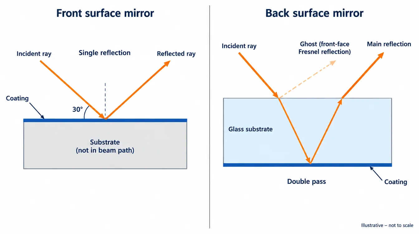
Because the substrate of a front surface mirror is outside the optical path, its transmission, homogeneity and bubble content have no optical effect. It can be opaque. Only the coated face needs an optical polish, and the material is chosen for stiffness, thermal expansion and stability of surface figure.
The substrate of a back surface mirror is an optical element. Both faces need an optical polish, the parallelism or wedge between them has to be controlled, and the bulk material has to transmit the working wavelengths.
| Mirror type | Coating position | Beam path | Ghost reflection | Usable band | Coating exposure |
|---|---|---|---|---|---|
| Front surface (first surface) | Face toward the source | Reflects at the coating, no substrate pass | None from the substrate | Set by the coating | Exposed to air, handling and cleaning |
| Back surface (second surface) | Face away from the source | Two passes through the substrate | Fresnel reflection from the front face | Set by coating and substrate transmission | Sealed behind the substrate |
Why does a back surface mirror produce a ghost image?
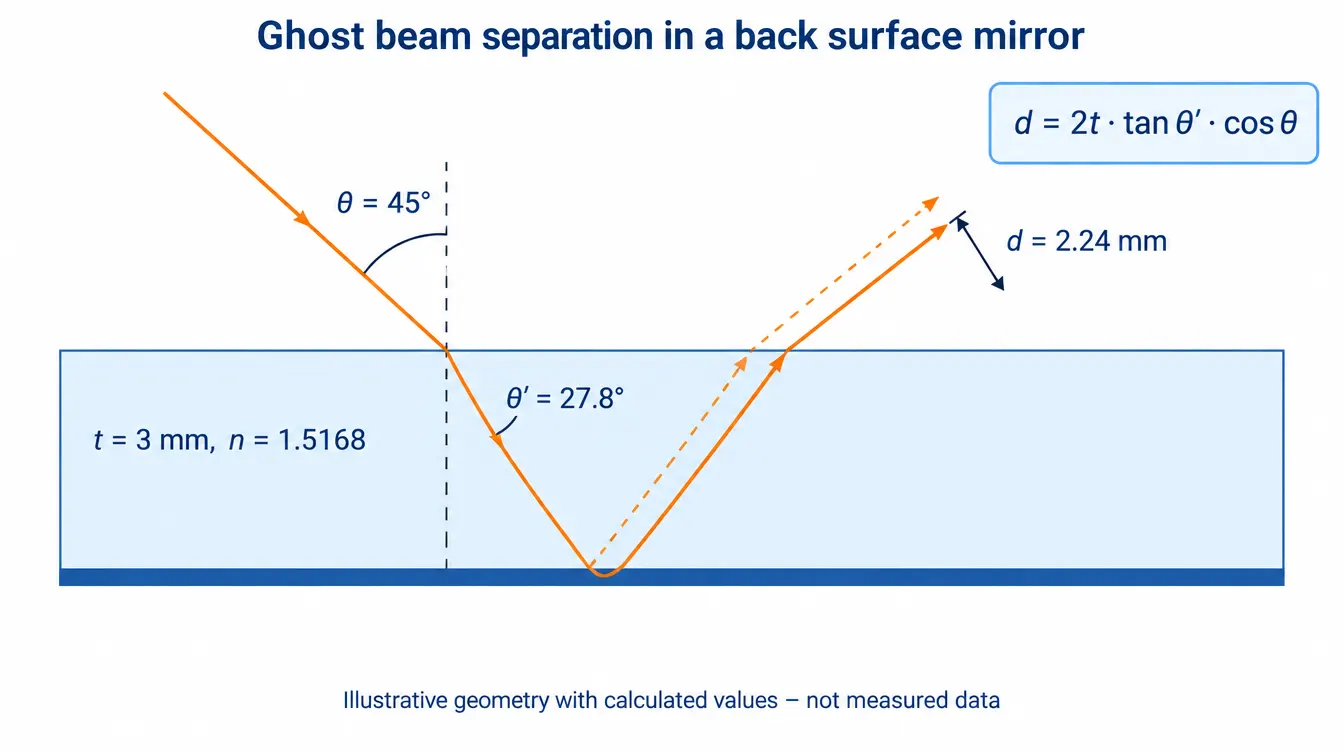
The front face of the substrate is an air-glass interface, and every such interface reflects part of the incident light. That Fresnel reflection leaves the mirror before the main beam has reached the coating. The result is two reflected beams from one incident beam: a strong one from the rear coating and a weak one from the front face.
At normal incidence the reflectance of an uncoated interface is R = ((n − 1) / (n + 1))². For a borosilicate crown glass with n = 1.5168 at 587.6 nm this gives R = 4.2%. Away from normal incidence the value depends on polarization. The figures below are calculated from the Fresnel equations for a lossless, uncoated, plane-parallel plate in air; they are not measured product data.
| AOI | Rs | Rp | Unpolarized | Beam separation |
|---|---|---|---|---|
| 0° | 4.2% | 4.2% | 4.2% | 0 mm |
| 30° | 6.1% | 2.7% | 4.4% | 1.81 mm |
| 45° | 9.6% | 0.92% | 5.3% | 2.24 mm |
Calculation inputs: n = 1.5168, substrate thickness t = 3 mm, air on the entrance side. Beam separation is the perpendicular distance between the ghost and the main reflected beam, d = 2t·tan θ′·cos θ, where θ is the AOI in air and θ′ the refraction angle in the glass.
How strong is the ghost relative to the main beam?
The main beam crosses the front face twice, so its intensity is (1 − R)²·Rm, where Rm is the reflectance of the coating seen from inside the glass. Taking R = 4.2% and an assumed Rm of 90% purely for the arithmetic, the main beam carries 82.6% of the incident power and the ghost is 5.1% of the main beam. A further beam appears after one more round trip inside the substrate, and the series continues with falling intensity.
For aluminium and silver in the visible, Rm is lower against glass than against air, because the reflectance of a metal depends on the index of the medium in front of it. A back surface metal mirror therefore returns less light than the same metal used as a front surface coating, before substrate absorption is counted.
When does the ghost appear as a double image?
With parallel faces the ghost leaves parallel to the main beam and laterally displaced. In a collimated beam that is later focused, both beams reach the same image point, so there is no doubled image; with coherent light they interfere and the reflected power varies with wavelength and substrate temperature. In converging or diverging beams, and when viewing a nearby object, the lateral displacement shows as a second, fainter image.
If the two faces have a wedge angle α, the two beams separate in angle. Near normal incidence and for small α, the angular separation is 2nα. A wedge of 1 arcminute in glass of n = 1.5168 gives 3.0 arcminutes between ghost and main beam, which is visible as a double image in a collimated imaging path.
What else does the substrate do to the beam in a back surface mirror?
A back surface mirror behaves like a front surface mirror with a glass plate of twice the substrate thickness placed in front of it. Everything a plate does to a beam applies: absorption, focus shift, aberrations in non-collimated light and dispersion. None of these exist in a front surface mirror.
- Spectral limit. The mirror only works where the substrate transmits. A crown glass substrate blocks deep UV and mid-infrared light regardless of what the coating could reflect.
- Focus shift. In a converging beam near normal incidence, the paraxial focus moves by 2t(1 − 1/n). For t = 3 mm and n = 1.5168 the shift is 2.04 mm.
- Aberrations. In a converging or diverging beam the plate adds spherical aberration. If the mirror is tilted, it also adds astigmatism, coma and lateral colour. In a collimated beam these terms vanish.
- Absorbed power. Light absorbed in the bulk heats the substrate. In a front surface mirror only the coating absorbs.
The plate behaviour can also be used on purpose. A Mangin mirror is a back surface mirror on a meniscus lens: the refraction at the front face is designed to cancel the spherical aberration of the spherical reflecting surface.
Which coatings are used on front surface and back surface mirrors?
Both types use the same reflecting metals, mainly aluminium, silver and gold. Front surface mirrors add thin dielectric layers on top of the metal for protection or higher reflectance, or replace the metal with an all-dielectric stack. Back surface mirrors rely on the substrate for protection on the optical side and a backing layer on the rear.
- Protected aluminium. Aluminium with a thin dielectric overcoat. It covers the ultraviolet through the near infrared, with a reflectance dip between 800 nm and 850 nm.
- Enhanced aluminium. Aluminium with a multilayer dielectric stack that raises reflectance over a limited band, at the cost of stronger dependence on wavelength and AOI.
- Protected silver. Higher reflectance than aluminium in the visible and near infrared. Reflectance falls steeply below 400 nm, and the coating tarnishes if the overcoat is breached.
- Protected gold. High reflectance in the infrared and chemically stable. It absorbs in the blue and green.
- Dielectric high reflector. An all-dielectric front surface stack with very low absorption inside its design band. The band is narrow compared with a metal, and it shifts with AOI and polarization.
For an overview of available configurations, see the optical mirrors family.
What are the trade-offs between front surface and back surface mirrors?
A front surface mirror gives a clean single reflection and exposes the coating. A back surface mirror protects the coating and puts glass in the beam. Neither is a higher grade of the other; each removes one problem and accepts another.
What the front surface mirror costs
The coating is the outermost layer. Metal films are soft, and the overcoats on them are thin, so scratches, pinholes, fingerprints and cleaning marks land directly on the reflecting surface. Unprotected silver also reacts with sulphur compounds in air. Cleaning has to follow the method allowed for the specific coating, and surface imperfection limits on the drawing apply to the functional surface itself.
What the back surface mirror costs
The ghost, the reduced throughput, the spectral limit of the substrate and the plate aberrations described above. An AR coating on the front face lowers the ghost within the AR design band and AOI range, and a deliberate wedge steers it out of the field, but both add a coating run or a tolerance and neither removes the double pass.
Where the back surface mirror is the better part
It fits applications where the surface will be wiped, touched or exposed to weather, and where a few percent of displaced stray light is acceptable: viewing and inspection mirrors, illumination folding, solar concentrators, and enclosures that are cleaned routinely. It also fits designs that use the refraction deliberately, such as Mangin elements. Reflecting prisms with a coated face work the same way: the coating sits behind glass, and the entrance face is AR coated to control the ghost. The same reasoning applies to plate beamsplitters, where the second face is the ghost source.
How do you choose between a front surface and a back surface mirror?
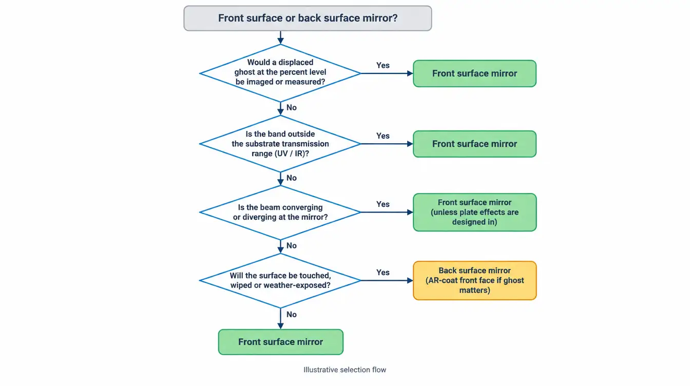
Start from what the system does with stray light and with the wavelength range, then check the environment. If a displaced secondary beam at the percent level would be detected, measured or imaged, the mirror has to be front surface. If the coating cannot survive the handling it will receive, the mirror has to be back surface or the design has to protect it another way.
- Imaging, machine vision folding, scanning and projection paths: front surface. A ghost at 5% of the main beam is a visible double edge.
- Laser beam steering and interferometry: front surface. The second reflection interferes with the main beam and the substrate absorbs power.
- Ultraviolet or infrared bands outside the transmission range of glass: front surface, since a back surface mirror cannot work there.
- Converging or diverging beams: front surface, unless the plate aberrations are part of the design.
- Exposed, frequently cleaned, non-imaging use: back surface, with an AR-coated front face if the ghost matters.
Common mistakes
- Ordering a “mirror” without stating the coating side. Commodity glass mirrors are back surface.
- Specifying reflectance without wavelength range, AOI and polarization. A reflectance figure without those conditions cannot be verified.
- Measuring a back surface mirror and reporting the sum of ghost and main beam as the mirror reflectance.
- Putting tight flatness on a front surface mirror and leaving substrate thickness to the supplier. Thin substrates bend under coating stress and mounting loads.
- Assuming a front surface mirror can be wiped like a window.
What should the drawing or RFQ state for each mirror type?
Both types need the coated side marked, the wavelength range, the AOI, the polarization state and the reflectance requirement under those conditions. Beyond that the lists diverge, because the substrate is mechanical in one case and optical in the other.
- Front surface mirror: substrate material and thickness, surface flatness or figure over the clear aperture, surface imperfection limits on the coated face, coating type and overcoat, rear face finish, cleaning and environmental requirements.
- Back surface mirror: substrate material and its transmission over the band, polish and surface imperfection limits on both faces, parallelism or specified wedge, front-face AR coating if required, coating and backing on the rear face, and the acceptable ghost level.
Reflectance verification should reproduce the stated AOI and polarization. GIAI reviews custom optical projects against the drawing, sample, optical requirements, substrate, geometry, coating conditions and inspection criteria before defining the manufacturing route; the review steps are described under quality assurance. Related component guides are collected in the lenses and optical components resources.
FAQ
What is the difference between a first surface and a second surface mirror?
A first surface mirror has its reflective coating on the face toward the incoming light, so the light reflects without entering the substrate. A second surface mirror has the coating on the rear face, so the light passes through the substrate twice. The second surface mirror protects its coating but adds a ghost reflection from the front face and limits the usable band to the substrate transmission range.
What are the main advantages of first surface mirrors?
First surface mirrors produce a single reflection with no ghost from the substrate, add no chromatic or plate aberrations, and work at any wavelength the coating reflects, including bands where glass is opaque. The substrate is outside the optical path, so it can be selected for stiffness and thermal stability, and only one face needs an optical polish.
Why are first surface mirrors so sensitive?
First surface mirrors are sensitive because the reflecting film is the outermost layer of the part. Metal coatings are soft and their dielectric overcoats are thin, so abrasion, fingerprints and unsuitable cleaning act directly on the functional surface. Unprotected silver also tarnishes in air. A back surface mirror avoids this by sealing the coating behind the substrate.
Which metals are used for first surface mirror coatings?
First surface mirror coatings use aluminium, silver and gold. Aluminium covers the ultraviolet through the near infrared. Silver gives higher reflectance in the visible and near infrared but falls steeply below 400 nm and needs a protective overcoat. Gold is used in the infrared and absorbs in the blue and green. All-dielectric stacks are an alternative where a narrow band is acceptable.
How can you tell if a mirror is front surface or back surface?
Bring a soft, non-marring pointed object close to the mirror at the edge, outside the clear aperture. On a back surface mirror a gap is visible between the tip and its reflection, equal to the optical depth of the substrate. On a front surface mirror the tip and its reflection meet. Viewing a small light source at an angle also shows the fainter ghost of a back surface mirror.
References
- ISO 10110-7, Optics and photonics — Preparation of drawings for optical elements and systems — Part 7: Surface imperfections.
- ISO 9211-1, Optics and photonics — Optical coatings — Part 1: Vocabulary.
- E. Hecht, Optics, Pearson. Chapters on the Fresnel equations and reflection from metals.
- H. A. Macleod, Thin-Film Optical Filters, CRC Press.
- M. Born and E. Wolf, Principles of Optics, Cambridge University Press. Optics of metals.
- A. D. Rakić, “Algorithm for the determination of intrinsic optical constants of metal films: application to aluminum,” Applied Optics 34(22), 4755–4767 (1995).
For a mirror project, send GIAI the drawing, optical specification or sample together with the wavelength range, substrate, dimensions, coating side and coating requirements, AOI and polarization, inspection criteria and expected quantity for technical review.