
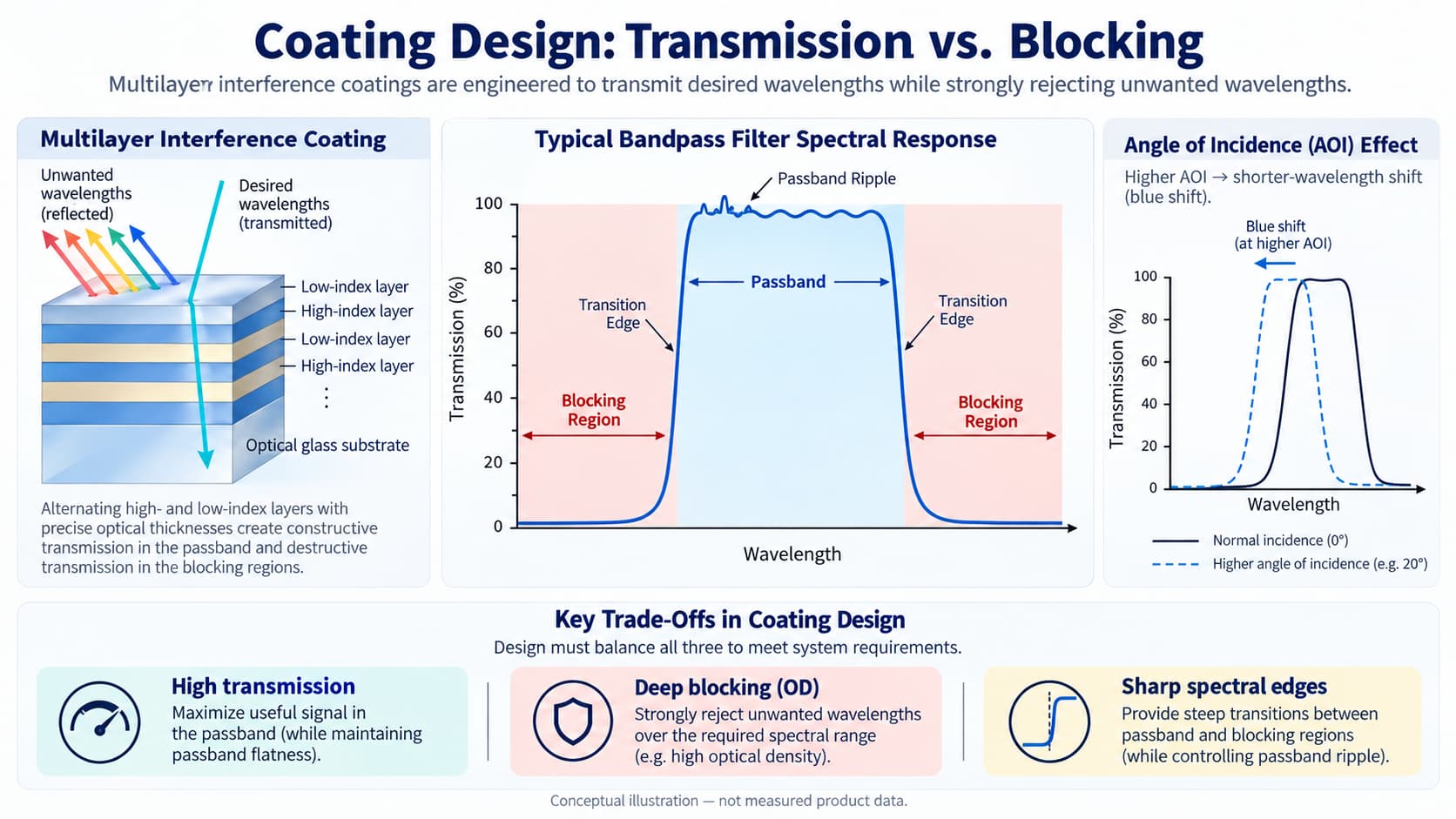
An optical filter may deliver excellent peak transmission at its specified wavelength yet still perform poorly in an imaging or sensing system. The problem is often not the transmission peak itself, but unwanted light leaking through other parts of the spectrum.
This is why optical coating design must balance two requirements: allowing sufficient light to pass through the intended spectral region while suppressing wavelengths that interfere with the measurement.
Coating design balances transmission and blocking by optimizing the refractive indices, optical thicknesses, and arrangement of thin-film layers to produce the required spectral response. The design must also account for passband ripple, blocking range, edge steepness, angle of incidence, polarization, and manufacturing tolerances.
Increasing blocking performance or sharpening a spectral edge is not automatically an improvement if it reduces usable signal transmission or makes the filter excessively sensitive to operating conditions.
How Thin-Film Coatings Control Transmission and Blocking
Most dielectric interference filters consist of multiple thin-film layers deposited onto an optical substrate. These layers have different refractive indices and carefully controlled optical thicknesses.
When light encounters an interface between two materials with different refractive indices, part of the light is reflected and part is transmitted.
Within a multilayer coating, reflected and transmitted waves interfere. Their relative phases depend on wavelength, refractive index, layer thickness, angle of incidence, and polarization.
By controlling these properties, designers can create a spectral response in which:
- Desired wavelengths experience high transmission.
- Unwanted wavelengths experience strong reflection and therefore low transmission.
- Transition regions separate the transmitting and blocking bands.
For a low-absorption dielectric coating, most rejected light is reflected rather than absorbed. This distinction matters in optical systems where reflected light may create stray-light paths or unwanted secondary reflections.
A bandpass filter, for example, can be designed to transmit a defined wavelength interval while rejecting shorter and longer wavelengths. Longpass and shortpass filters use related interference principles to establish a spectral transition between transmitting and blocking regions.
The important point is that the entire spectral response comes from the multilayer structure, not from one individual coating layer.
Why Maximum Transmission Is Not the Only Design Target
High transmission is important because optical systems typically have limited signal budgets.
In fluorescence imaging, the detected emission may be weak. In machine vision, reducing unwanted optical losses can help maintain exposure time and signal-to-noise ratio. In optical sensing, additional transmission loss can reduce the useful signal reaching the detector.
However, peak transmission alone does not describe filter performance.
Consider two hypothetical bandpass filters operating in the same imaging system.
Filter A has a higher transmission peak but a narrower usable passband and greater transmission variation across that band.
Filter B has a slightly lower peak but maintains more uniform transmission across the wavelengths produced by the light source.
Depending on the source spectrum and detector sensitivity, Filter B may deliver more useful signal.
This illustrates the distinction between peak transmission, average transmission, and minimum transmission.
Peak Transmission vs. Average Transmission
Peak transmission identifies the maximum transmittance reached somewhere within the passband.
Average transmission describes the transmission averaged over a specified wavelength interval.
Minimum transmission defines a lower limit that must be satisfied throughout the required passband.
For a broadband LED or fluorescence emission spectrum, average or minimum transmission across the useful spectral region may be more meaningful than the highest transmission at a single wavelength.
Ideally, engineers should also consider the source spectrum and detector response when assessing usable throughput.
A coating that performs well on a nominal transmission curve may not provide the same benefit when installed in the actual optical system.
How Optical Density Defines Blocking Performance
Blocking describes how effectively a filter suppresses unwanted wavelengths.
It is commonly specified using optical density (OD), defined from the transmitted fraction of incident light:
OD = −log₁₀(T)
Here, T is the transmittance expressed as a fraction rather than a percentage.
For example:
| Optical Density | Transmission | Attenuation Factor |
|---|---|---|
| OD2 | 1% | 100× |
| OD3 | 0.1% | 1,000× |
| OD4 | 0.01% | 10,000× |
| OD5 | 0.001% | 100,000× |
| OD6 | 0.0001% | 1,000,000× |
These are mathematical relationships, not specifications for a particular GIAI product.
A higher OD indicates lower transmitted light at the wavelength being evaluated. It does not, however, establish that the same blocking performance is maintained across the entire spectrum.
Why the Blocking Range Matters
Suppose a sensing system operates near 850 nm.
The detector may also respond to visible illumination and neighboring near-infrared wavelengths. A filter that provides strong blocking at a few selected wavelengths may still permit interference elsewhere within the detector’s sensitivity range.
Therefore, a complete blocking specification should define both:
- The required optical density.
- The wavelength range over which that density must be maintained.
For example, specifying OD4 without a blocking wavelength range leaves a critical part of the optical requirement undefined.
The required blocking level should be determined from the unwanted-light spectrum, detector response, acceptable background signal, and measurement conditions.
Extending deep blocking across a wider spectral interval may also require a more complex coating design or supplementary filtering elements.
The Main Trade-Offs in Optical Coating Design
Transmission and blocking are not entirely independent performance parameters.
The multilayer structure must satisfy several competing requirements, and improving one characteristic can make another more difficult to maintain.
| Design Objective | Potential Trade-Off |
|---|---|
| Higher passband transmission | May require changes that affect passband flatness or other spectral constraints |
| Deeper out-of-band blocking | May increase coating complexity and sensitivity to manufacturing errors |
| Wider blocking range | May require additional coating structures or supplementary blocking elements |
| Steeper spectral edges | Can increase passband ripple or sensitivity to layer-thickness errors |
| Reduced AOI sensitivity | May constrain passband width, edge steepness, or other design targets |
| Lower reflected stray light | May require absorbing elements that introduce transmission loss |
These relationships depend on the coating architecture, materials, and constraints. They are not universal one-to-one rules.
1. Edge Steepness vs. Passband Ripple
A steep spectral edge allows a filter to transition rapidly from high transmission to strong blocking.
This is particularly valuable when the desired signal lies close to an unwanted wavelength.
For a multilayer structure with a fixed number of layers, optimizing for steeper transition edges can increase oscillations in the transmission band.
These oscillations are commonly described as passband ripple.
Reducing ripple while preserving steep edges may require additional design freedom, such as a more complex layer structure.
More layers, however, can increase deposition time, accumulated coating stress, and sensitivity to manufacturing tolerances.
The practical objective is not necessarily to obtain the steepest possible edge. It is to obtain enough separation between desired and unwanted wavelengths without compromising the usable signal.
2. Deep Blocking vs. Coating Complexity
Strong blocking results from the collective optical response of the multilayer structure.
Increasing the number of layers or introducing additional blocking structures can help extend rejection performance, depending on the design.
However, coating complexity introduces manufacturing considerations.
Small deviations in refractive index or deposited thickness can alter the spectral response. Thickness variations across the substrate may also produce spatial differences in center wavelength or spectral edges.
A design that performs well in an ideal simulation must therefore be evaluated for its sensitivity to realistic production variations.
Coating thickness and film stress also matter, especially when the substrate is thin or geometrically sensitive.
3. Broad Blocking vs. Passband Throughput
A bandpass coating does not necessarily provide deep blocking at every wavelength outside its transmission band.
Its blocking performance is finite in spectral extent.
If an application requires rejection across a very broad wavelength range, additional blocking structures may be needed.
Depending on the design, this can involve supplementary coatings, substrate absorption, or multiple optical elements.
These approaches may improve unwanted-light suppression while introducing additional optical loss, complexity, or mechanical constraints.
The correct solution depends on which wavelengths actually matter to the system.
Blocking wavelengths outside the detector’s sensitivity range may provide little practical benefit unless another system requirement justifies it.
Angle of Incidence and Polarization Change the Balance
A coating optimized at normal incidence may behave differently when illuminated at an oblique angle.
For many interference filters, increasing the angle of incidence shifts spectral features toward shorter wavelengths. This is commonly called a blue shift.
The shift results from changes in the phase accumulated by light propagating through the multilayer structure.
This can affect both the transmitting and blocking portions of the spectrum.
For example, a bandpass filter designed around a nominal wavelength at normal incidence may exhibit a shifted transmission band when installed in a tilted optical path.
As a result, useful wavelengths near one passband edge may experience lower transmission, while unwanted wavelengths near the opposite edge may experience less blocking.
Why Beam Geometry Matters
In a real optical system, not every ray necessarily strikes the filter at the same angle.
A converging or diverging beam contains a distribution of incidence angles. Each ray can experience a somewhat different spectral response.
The combined effect may reduce effective peak transmission, broaden or distort spectral features, and weaken wavelength discrimination.
This is why specifying only the nominal AOI may be insufficient for filters installed in fast imaging optics.
The beam cone or angular distribution should also be considered.
Polarization Effects
At oblique incidence, s-polarized and p-polarized light generally experience different optical responses.
Their spectral edges and passband shapes may separate.
For an optical system using polarized light, the relevant polarization state should be included in the coating specification.
For systems using unpolarized or partially polarized light, the performance requirements should account for the relevant polarization components and their distribution.
A spectral curve measured at normal incidence does not automatically establish performance at an oblique working angle.
How Application Requirements Influence Coating Design
The required balance between transmission and blocking changes with the optical system.
Fluorescence Detection
Fluorescence systems often need to detect relatively weak emission in the presence of much stronger excitation light.
The emission filter must transmit useful fluorescence wavelengths while sufficiently suppressing excitation light and other unwanted radiation.
Deep blocking may be especially important where the excitation spectrum approaches the emission band.
However, narrowing the emission passband excessively can also remove useful fluorescence photons.
Filter selection should therefore consider excitation and emission spectra, detector sensitivity, and the full optical path.
Machine Vision
Machine vision systems frequently combine controlled illumination with cameras sensitive to a broader wavelength range.
A bandpass filter can improve contrast by passing useful illumination wavelengths while suppressing ambient light.
The coating must accommodate the source’s actual spectral width, not simply its nominal center wavelength.
The lens geometry, AOI distribution, and detector response also affect performance.
Deep blocking may improve ambient-light rejection, but excessively narrow transmission can reduce useful illumination when the LED spectrum or operating conditions vary.
LiDAR and Optical Sensing
Optical sensing systems may need to distinguish reflected source light from sunlight or other background radiation.
Bandpass filtering can reduce the unwanted optical power reaching the detector.
In this application, transmission efficiency, spectral bandwidth, blocking range, and angular response must be considered together.
For a receiver with a wide field of view or a significant angular spread at the filter, the coating must be evaluated under the relevant beam geometry.
The highest nominal transmission at a single wavelength is not sufficient to determine system performance.
How Engineers Should Specify Transmission and Blocking
A useful coating specification describes what the finished optical element must do under defined operating and measurement conditions.
It should not merely request the highest possible transmission and optical density.
A practical specification should address the following:
| Parameter | What Should Be Defined |
|---|---|
| Operating wavelength | Required signal wavelength or spectral region |
| Passband | Minimum and maximum wavelengths that must be transmitted |
| Transmission | Peak, minimum, or average transmission requirement |
| Blocking range | Specific out-of-band wavelength intervals |
| Optical density | Minimum OD across each defined blocking interval |
| Spectral edges | Required transition locations and edge steepness |
| AOI | Nominal angle and operating angular range |
| Beam geometry | Collimated, converging, or diverging illumination |
| Polarization | s, p, unpolarized, or application-specific state |
| Substrate | Material, dimensions, thickness, and related requirements |
| Clear aperture | Area over which the optical specification must apply |
| Environment | Relevant temperature, humidity, or operating conditions |
| Verification | Measurement conditions and acceptance criteria |
Not every application requires the same degree of specification detail.
The purpose is to define the parameters that materially influence system performance and determine which requirements are essential versus negotiable.
When several demanding specifications conflict, engineers may need to adjust the passband, revise the blocking range, change the optical layout, or evaluate a different filtering architecture.
Why Coating Verification Must Match the Design Conditions
Coating design is only one part of obtaining a functional optical filter.
The manufactured component must be inspected under conditions that meaningfully correspond to the intended application.
For wavelength-selective coatings, verification may include transmission spectra, reflection spectra, blocking performance, spectral edge locations, and AOI-dependent measurements.
There is also an important distinction between predicting high optical density and measuring it.
Very low transmittance can approach the detection limits of conventional spectral measurement equipment.
The spectral bandwidth of the instrument, stray light, detector noise floor, and angular distribution of the measuring beam can influence the result.
Consequently, very high OD requirements may need an appropriate verification strategy rather than relying on an ordinary spectral scan alone.
A reported blocking value should be accompanied by sufficient information about the measurement wavelength, measurement method, and applicable conditions.
Similarly, a single transmission curve cannot establish performance across a wide range of incidence angles unless the design and validation data support that conclusion.
How GIAI Approaches Custom Optical Coating Requirements
GIAI Photonics works with precision optical components and project-specific optical coating requirements, including wavelength-selective filters and other coated optical elements.
For a custom filter project, the engineering review starts with the application requirements rather than assuming that one standard coating design will satisfy every optical system.
Relevant inputs may include the intended passband, transmission requirements, blocking range, optical density, substrate, component dimensions, angle of incidence, polarization, and inspection criteria.
These inputs help establish the feasibility of the required spectral response and the appropriate manufacturing and verification route.
For related information, explore GIAI’s Optical Filters, Manufacturing Capabilities, and Quality Assurance resources.
If your project involves a coating design with demanding transmission and blocking requirements, you can submit the optical specifications, drawings, or reference samples through the GIAI contact page for project-level evaluation.
Actual achievable performance and acceptance criteria must be established for the specific design and operating conditions.
Frequently Asked Questions
Can an optical coating achieve both high transmission and high optical density?
Yes. Dielectric multilayer interference coatings can combine high transmission in a specified passband with strong rejection outside that band. The achievable combination depends on wavelength range, spectral edge requirements, AOI, coating materials, and manufacturing constraints.
Does increasing the number of coating layers always improve blocking?
No. Additional layers provide more design freedom and may improve certain spectral characteristics, but layer arrangement and thickness control are equally important. More layers can also increase manufacturing complexity, stress, and sensitivity to errors.
Why does a filter perform differently after installation?
A change in incidence angle, beam cone, or polarization can alter the spectral response of an interference filter. The installed system may therefore transmit and reject different wavelengths than a normal-incidence laboratory measurement suggests.
Should transmission or blocking be prioritized in an optical filter?
Neither should be maximized independently. The priority depends on the source intensity, required signal, unwanted-light spectrum, detector response, and acceptable noise level. The most effective design meets the system’s actual optical requirements with an appropriate performance margin.
Conclusion
Balancing transmission and blocking is one of the central challenges in optical coating design.
High passband transmission preserves useful optical signals, while effective blocking reduces unwanted light. Achieving both requires careful control of multilayer interference, spectral edge behavior, angular sensitivity, polarization, and manufacturing tolerances.
For optical engineers, the goal should not be the highest possible transmission or optical density in isolation. It should be a coating specification that delivers the required spectral performance under real operating conditions and can be verified using an appropriate measurement method.
References and Further Reading
- RP Photonics Encyclopedia, article on “Interference Filters”, Dr. Rüdiger Paschotta,
- Murphy, D. B., Spring, K. R., Parry-Hill, M. J., and Davidson, M. W. Interference Filters — Microscopy Resource Center.
- Ziter, M., Carver, G., Locknar, S., Upton, T., and Johnson, B. Laser-based assessment of optical interference filters with sharp spectral edges and high optical density. Surface and Coatings Technology, 241, 54–58 (2014).
- Qi, H., Hong, R., Yi, K., Shao, J., and Fan, Z. Nonpolarizing and polarizing filter design. Applied Optics, 44(12), 2343–2348 (2005).