
A narrowband optical filter may meet its wavelength specifications during laboratory testing but behave differently after installation in an optical system. One possible reason is a difference in the angle at which light reaches the filter.
This angle is known as the angle of incidence (AOI), and it is an important parameter in optical design, thin-film coating performance, and component inspection.
What Is Angle of Incidence (AOI) in Optics?
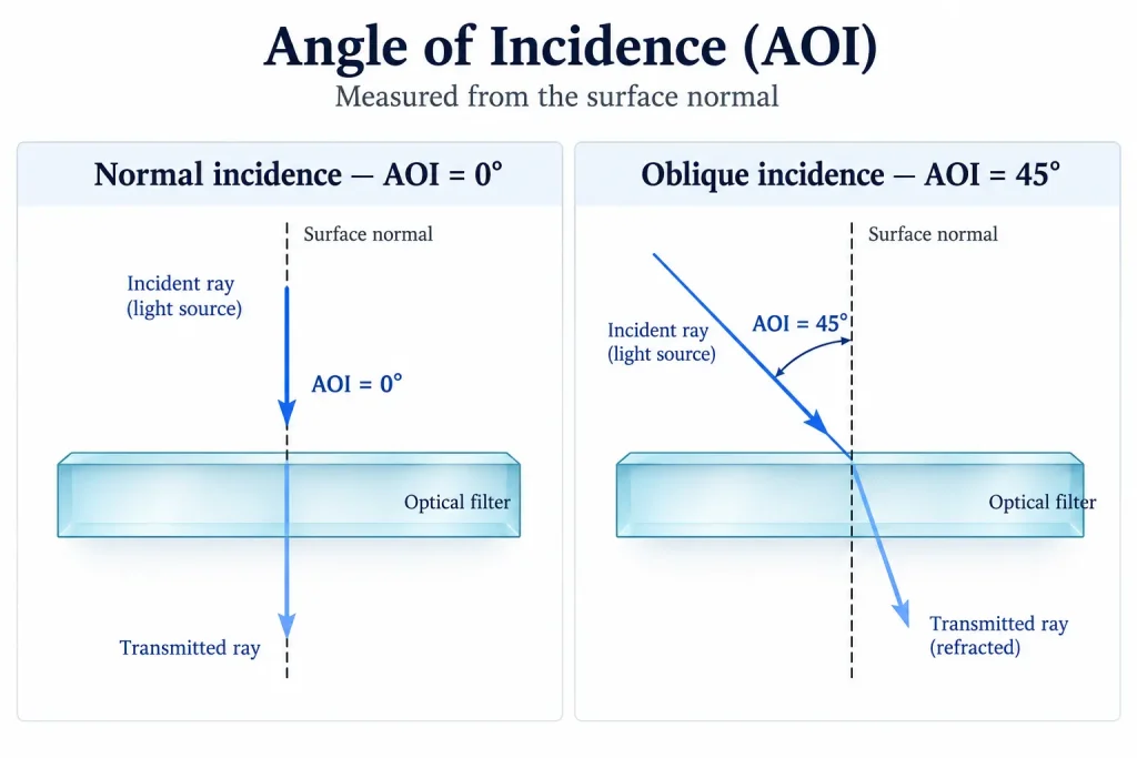
Angle of incidence (AOI) is the angle between an incoming light ray and the surface normal at the point where the ray strikes an optical surface. The surface normal is an imaginary line perpendicular to that surface.
AOI is measured in degrees (°).
- 0° AOI: Light strikes the surface perpendicularly. This is called normal incidence.
- 15° AOI: The incoming ray forms a 15° angle with the surface normal.
- 45° AOI: Light reaches the surface at 45° to the normal. This geometry is commonly used with dichroic mirrors and beamsplitters.
- 90° AOI: The limiting case of grazing incidence, where the ray travels parallel to the surface.
An important distinction is that AOI is measured relative to the surface normal, not the surface itself.
For example, a ray that forms a 30° angle with a flat optical surface has an AOI of 60°.
For a curved optical element, the relevant normal is the local normal at the point of incidence. Consequently, AOI can vary across a lens or another nonplanar optical surface.
Why Does Angle of Incidence Matter?
AOI influences how light interacts with an optical component.
The effects depend on the optical material, surface geometry, coating structure, wavelength, and polarization state.
For an uncoated transparent interface, the incidence angle affects reflection and refraction. For a multilayer interference coating, it also affects the phase relationships that determine its spectral response.
This distinction is especially important for optical filters.
A filter designed and characterized at normal incidence may not maintain the same center wavelength, transmission, or blocking performance when used at an oblique angle.
AOI therefore needs to be considered during component selection rather than treated as an installation detail.
How Does AOI Affect Optical Filter Performance?
1. Center wavelength shift
Many thin-film interference filters use alternating layers of optical materials to control which wavelengths are transmitted or reflected.
Their spectral response depends on the optical phase accumulated as light propagates through the multilayer structure.
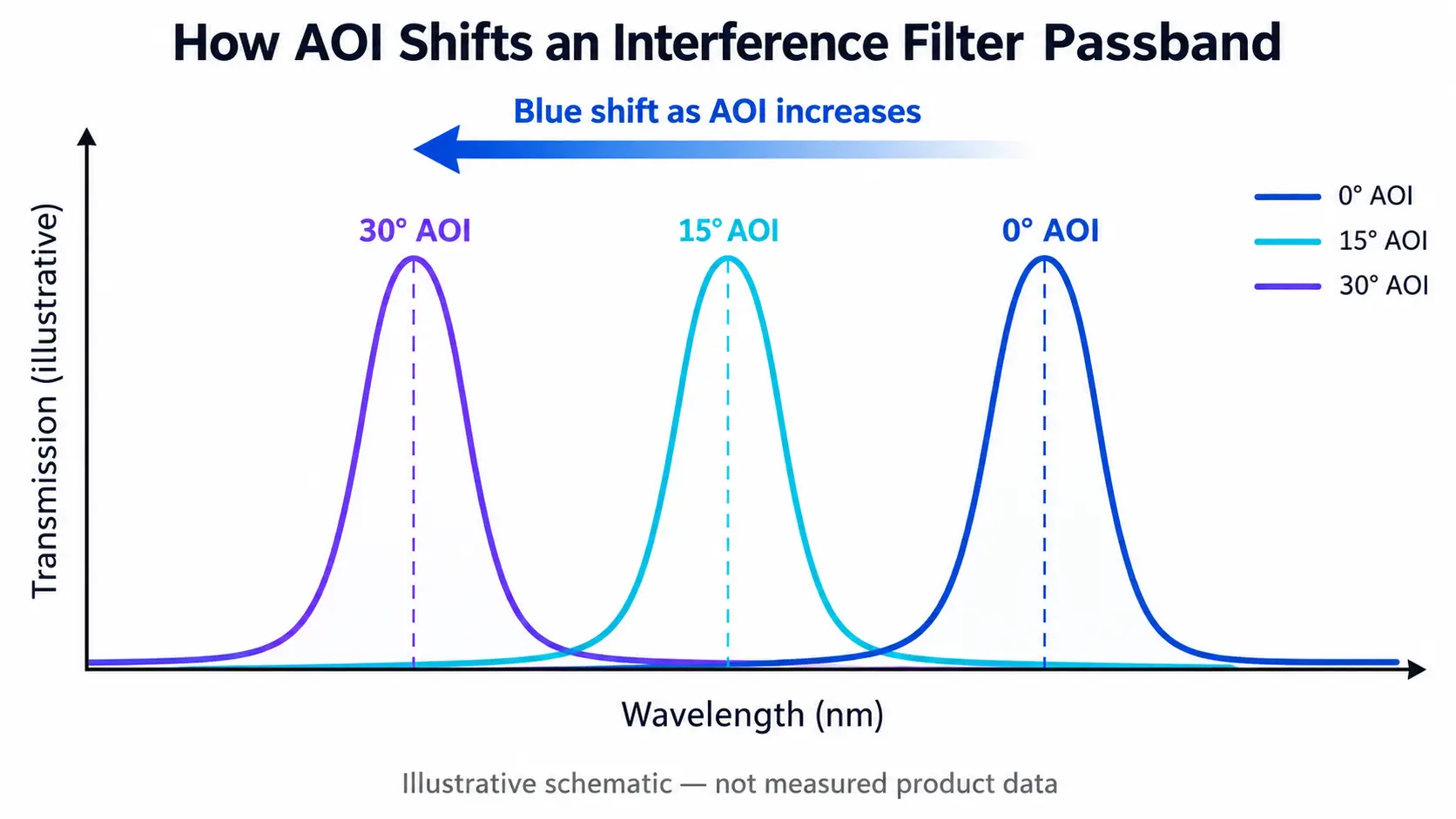
When the angle of incidence increases from normal incidence, the phase conditions within the coating change.
For conventional interference bandpass filters, this generally causes the transmission band to move toward shorter wavelengths, an effect known as blue shift.
Consider a bandpass filter designed with a center wavelength of 850 nm at 0° AOI.
If the same filter is tilted away from normal incidence, its transmission peak will generally shift below 850 nm.
The exact shift depends on the coating design and optical conditions. It cannot be determined reliably from the nominal wavelength alone.
This behavior matters particularly for narrowband filters because a relatively small wavelength displacement may represent a substantial fraction of the specified bandwidth.
2. Transmission and spectral shape
Changing AOI can affect more than the center wavelength.
Depending on the coating design and operating angle, the spectral response may exhibit changes in:
- Peak transmission
- Full width at half maximum (FWHM)
- Passband shape and edge steepness
- Reflection characteristics
- Blocking performance at specified wavelengths
A filter that satisfies its transmission requirement at one angle may not satisfy the same requirement at another.
These changes should be evaluated against the actual operating wavelength and spectral acceptance criteria rather than assuming that an entire transmission curve shifts without changing shape.
3. Polarization-dependent behavior
At oblique incidence, the interaction between light and a multilayer optical coating can depend on polarization.
Two polarization components are commonly considered:
S-polarization: The electric field is perpendicular to the plane of incidence.
P-polarization: The electric field is parallel to the plane of incidence.
For an isotropic planar multilayer at normal incidence, these two polarization states have the same optical response.
At non-normal incidence, their transmission and reflection characteristics may differ.
For interference filters, the spectral features associated with S- and P-polarization can move by different amounts. This may produce polarization-dependent wavelength separation, changes in transmission, or modifications to the passband shape.
The effect becomes particularly relevant when evaluating dichroic filters, beamsplitters, and narrowband interference coatings designed for oblique operation.
For a more detailed explanation, see How Polarization Affects Optical Filter Spectra at Oblique Incidence.
How to Estimate Wavelength Shift Caused by AOI
For many interference filters operating in a collimated beam, a common first-order approximation for angular wavelength shift is:
λ(θ) ≈ λ₀ × √[1 − (n₀ sinθ / n_eff)²]
Where:
| Symbol | Meaning |
|---|---|
| λ(θ) | Approximate wavelength at incidence angle θ |
| λ₀ | Wavelength at normal incidence |
| θ | External angle of incidence |
| n₀ | Refractive index of the incident medium |
| n_eff | Effective refractive index associated with the filter design |
The effective refractive index is a design-dependent parameter. It should not automatically be replaced with the refractive index of the filter substrate.
Calculation example: an 850 nm bandpass filter
Assume a hypothetical interference filter has:
| Parameter | Illustrative value |
|---|---|
| Center wavelength at 0° | 850 nm |
| Incident medium | Air, n₀ ≈ 1 |
| Effective refractive index | 1.8 |
| Operating AOI | 15° |
Using the approximation:
λ(15°) ≈ 850 × √[1 − (sin15° / 1.8)²]
Calculated wavelength ≈ 841.2 nm
The estimated blue shift is approximately 8.8 nm.
This is an illustrative theoretical calculation, not a measured GIAI product result.
A real filter may behave differently because its effective optical properties depend on the multilayer design, wavelength, and polarization. At larger incidence angles, the simplified approximation may become insufficient.
Accurate evaluation may require a polarization-aware thin-film model or measured transmission data at the specified operating angle.
AOI vs. Cone Half Angle: What Is the Difference?
One of the most common specification problems is confusing the nominal angle of incidence with the range of angles present in a real optical beam.
AOI describes the incidence direction of a particular ray. Cone half angle describes the angular spread of a beam around its central direction.
For a collimated beam, the rays are approximately parallel, so they can strike a flat filter at nearly the same AOI.
For a converging or diverging beam, different rays reach the filter at different angles.
Even when the central ray has an AOI of 0°, off-axis rays may strike the filter at nonzero angles.
This angular distribution is important because different rays may experience different spectral shifts.
The resulting system response can therefore be broader or less sharply defined than the transmission curve measured with a single collimated beam.
This is particularly relevant in compact imaging systems, fluorescence instruments, machine vision cameras, and other optical assemblies where filters are placed in non-collimated light paths.
A complete filter specification should distinguish the nominal AOI from the range of ray angles experienced in operation.
How AOI Affects Different Optical Components
Although the basic definition of AOI applies to any optical surface, its practical importance differs among optical components.
| Optical component | Why AOI matters |
|---|---|
| Bandpass filter | Influences center wavelength and passband characteristics |
| Longpass or shortpass filter | Changes spectral edge positions in interference-based designs |
| Dichroic mirror | Affects wavelength separation, reflection, transmission, and polarization |
| Beamsplitter | Can change reflection/transmission ratios and polarization behavior |
| AR-coated lens or window | Influences reflection losses over the operating wavelength range |
| Optical mirror | Affects beam geometry and, depending on coating design, reflectance and polarization response |
For example, a dichroic mirror may be designed to operate at 45° AOI to separate transmitted and reflected light into different optical paths.
A 45°-design coating should not be assumed to provide its specified performance when operated at 0°, and the reverse is also true.
Similarly, an anti-reflection coating optimized for near-normal incidence may not maintain the same reflectance across a wide range of oblique angles.
The coating design angle and actual system angle must therefore be considered together.
How to Specify AOI for an Optical Filter
A filter drawing or procurement specification should define the angle under which the component must meet its optical requirements.
Simply providing a center wavelength and transmission target may be insufficient.
The relevant parameters include the nominal AOI, minimum and maximum incidence angles, beam geometry, operating polarization, and the spectral characteristics that must be maintained across those conditions.
Example: a filter used at normal incidence
An illustrative specification might state:
AOI: 0° nominal; operating ray angles: 0°–5°.
If the optical beam includes a range of angles, the required transmission and blocking performance should be evaluated over that range.
Example: a filter used at oblique incidence
A different system might require:
AOI: 45° nominal; operating range: 43°–47°.
For this application, the specification may need to define S- and P-polarized transmission or reflection separately.
These angular ranges are examples of specification formats, not standard tolerances or verified GIAI product ratings.
For an actual custom component, the acceptable angle range must be established from the optical system requirements.
Verify the spectrum under realistic conditions
Optical testing should correspond to the agreed component specification.
For angle-sensitive interference filters, a transmission curve measured at 0° cannot automatically demonstrate compliance with performance requirements at 15° or 45°.
Depending on the application, verification may require measurements or calculated performance data at the nominal operating AOI, the specified angular limits, and relevant polarization states.
Beam divergence and cone angle may also need to be included.
See GIAI’s Quality Assurance information for the company’s project-based approach to optical verification and inspection.
Common Mistakes When Working With AOI
Measuring the angle from the surface instead of the normal. AOI is defined relative to the perpendicular surface normal. Confusing these reference directions can produce a substantial specification error.
Assuming a 0° transmission curve applies at every angle. This is particularly problematic for wavelength-selective interference coatings.
Ignoring the cone angle. A beam may have a nominal AOI of 0° while containing many rays that strike the filter obliquely.
Using one assumed effective refractive index for every coating. Angular spectral shift depends on the actual multilayer design and cannot always be predicted from a generic material value.
Ignoring polarization in oblique systems. A filter characterized with unpolarized light may not deliver the same spectral response for a polarized laser beam.
Avoiding these errors begins with defining the real optical geometry before finalizing the component specification.
Frequently Asked Questions About Angle of Incidence
Is AOI measured from the surface or the normal?
AOI is always measured from the local surface normal, which is perpendicular to the optical surface at the point of incidence.
What is normal incidence in optics?
Normal incidence means AOI = 0°. The incoming light travels perpendicular to the optical surface.
Does increasing AOI always cause a blue shift?
Blue shift is characteristic of many conventional interference-filter spectral features as the incidence angle increases from normal. It is not a universal rule for every optical component or coating design.
Absorptive filters, for example, select wavelengths through material absorption rather than the same multilayer interference mechanism.
Why are some optical filters specified at 45° AOI?
Dichroic filters and certain beamsplitters are commonly designed for 45° operation because this geometry enables convenient separation of transmitted and reflected optical paths.
Their coatings must be designed and characterized for the intended operating angle.
Can tilting an optical filter be used to adjust its wavelength?
Tilting an interference filter can shift its spectral response and may be useful in certain wavelength-tuning applications.
However, tilt can also change transmission, bandwidth, blocking behavior, and polarization sensitivity. The usable tuning range must be assessed for the specific filter design.
Defining AOI for Custom Optical Components
The angle of incidence is a fundamental part of an optical specification, especially for wavelength-selective thin-film coatings.
When developing a custom optical filter, defining the actual operating AOI helps prevent differences between laboratory measurements and installed system performance.
At GIAI Photonics, custom optical projects can be reviewed against drawings, samples, optical requirements, substrate characteristics, geometry, coating conditions, and inspection criteria.
For angle-sensitive optical components, the project review should establish the relevant incidence angles, polarization conditions, spectral targets, and verification requirements before determining the manufacturing approach.
Explore GIAI’s Optical Filters or contact the team with your optical specifications for a project-level feasibility review.