
Choosing a bandpass filter manufacturer involves more than selecting a filter with the right center wavelength. In a real optical system, the finished filter may also need to meet requirements for bandwidth, transmission, blocking, optical density, angle of incidence, beam geometry, polarization, substrate, dimensions and inspection conditions.
For custom projects, these parameters should be evaluated together. A filter that performs correctly at one measurement condition may behave differently after it is installed in the actual optical path.
The practical question is therefore not simply:
“Can you manufacture an 850 nm or 532 nm bandpass filter?”
A better question is:
“Can the filter be designed, manufactured and verified for the wavelength, geometry and detector conditions of my system?”
What Should a Bandpass Filter Manufacturer Be Able to Define?
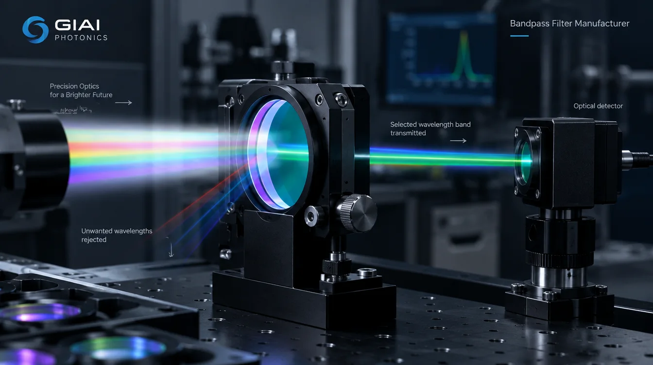
A bandpass filter transmits a selected spectral region while attenuating wavelengths outside that region.
For many optical systems, however, specifying only a nominal wavelength is not enough.
A useful custom specification normally considers:
| Parameter | What It Defines | Why It Matters |
|---|---|---|
| Center Wavelength (CWL) | Position of the passband | Aligns the filter with the required optical signal |
| FWHM / Bandwidth | Width of the transmitted region | Controls spectral selectivity |
| Passband Transmission | Amount of useful light transmitted | Affects optical throughput and signal level |
| Blocking Range | Wavelength range to be rejected | Determines which unwanted wavelengths are suppressed |
| Optical Density (OD) | Required attenuation in the blocking region | Helps control unwanted optical background |
| Angle of Incidence (AOI) | Angle at which light reaches the filter | Can affect interference-filter spectral position |
| Beam Geometry | Angular distribution of incident rays | Important for converging or diverging beams |
| Polarization | Polarization state of incident light | Can become important at oblique incidence |
| Substrate | Optical material supporting the coating | Affects transmission and component design |
| Clear Aperture | Usable optical area | Must accommodate the actual beam |
| Dimensions | Mechanical size and thickness | Determines system integration |
| Inspection Conditions | How performance will be measured | Establishes acceptance criteria |
The correct specification depends on the complete optical system rather than on any one parameter.
Bandpass Filters and Narrow Bandpass Filters
A bandpass filter transmits a defined wavelength interval and suppresses wavelengths on both sides of that interval.
A narrow bandpass filter performs the same basic function but uses a narrower transmission region.
There is no single bandwidth value that separates every narrow bandpass filter from every broader bandpass design. The useful bandwidth depends on the signal being detected and the amount of unwanted spectral energy that must be rejected.
A narrower bandwidth is therefore not automatically better.
If the passband becomes too narrow for the actual source spectrum, some useful signal may be lost. At the same time, tighter bandwidth requirements can make wavelength tolerance, AOI and beam geometry increasingly important.
The appropriate FWHM should be selected from the optical system requirement rather than from the assumption that smaller is always better.
Why Center Wavelength Alone Is Not Enough
Consider a request for:
“850 nm bandpass filter.”
That statement identifies the approximate spectral region but leaves several engineering questions unanswered.
For example:
- How wide should the passband be?
- What transmission is required?
- Over which wavelengths is blocking required?
- What OD level is necessary?
- At what AOI will the filter operate?
- Is the light collimated or converging?
- What wavelengths can the detector actually detect?
- What dimensions are required?
- How will the filter be inspected?
Two filters can share the same nominal center wavelength while behaving very differently in the final optical system.
For manufacturer evaluation, the full spectral requirement is therefore more useful than the wavelength label alone.
Passband Transmission Should Be Defined Clearly
“High transmission” is not a complete engineering specification.
Transmission can refer to several different quantities:
- peak transmission;
- minimum transmission;
- average transmission;
- transmission at the center wavelength;
- transmission across a defined wavelength interval.
These are not interchangeable.
A filter can have high peak transmission while having lower transmission near the edges of the required signal band.
If the source has a finite spectral width rather than a single wavelength, engineers should consider how much of the complete signal spectrum must pass through the filter.
A more useful requirement could therefore define a minimum or average transmission across the actual working band.
Blocking Range and OD Should Be Specified Together
Optical density describes attenuation.
It is commonly expressed as:
OD = −log₁₀(T)
where T is fractional transmittance.
For example:
| Optical Density | Fractional Transmission | Percentage Transmission |
|---|---|---|
| OD2 | 10⁻² | 1% |
| OD3 | 10⁻³ | 0.1% |
| OD4 | 10⁻⁴ | 0.01% |
| OD5 | 10⁻⁵ | 0.001% |
But an OD value alone does not define a complete blocking specification.
For example:
“OD4 blocking”
still leaves an important question:
OD4 over which wavelength range?
The required blocking interval should be based on the wavelengths that can interfere with the actual measurement.
This usually means considering:
source spectrum + optical path + detector response.
A detector that remains sensitive far outside the desired signal band may require a wider blocking range than a detector whose response is already limited to a narrow spectral region.
For this reason, deeper or broader blocking should be specified because the system requires it—not simply because a larger OD number looks better on a datasheet.
Why AOI Matters for Bandpass Filters
For thin-film interference bandpass filters, angle of incidence can influence the spectral response.
When the filter is used at an angle different from its design condition, spectral features generally shift toward shorter wavelengths as AOI increases.
This is particularly important when a filter is mounted at an intentional tilt or used in a system where rays reach the surface over a range of angles.
A filter measured near normal incidence should therefore not automatically be assumed to provide exactly the same spectral response at a significantly different AOI.
For a custom filter project, engineers should specify the intended operating angle early in the design process.
Converging and Diverging Beams Need Additional Attention
AOI is not always represented by one single angle.
In a collimated beam, most rays may reach the filter at approximately the same incidence angle.
In a converging or diverging beam, however, different rays can strike the filter at different angles.
As a result, different portions of the beam may experience slightly different spectral responses.
Depending on the optical design, this can affect:
- effective passband position;
- bandwidth;
- spectral edge shape;
- system throughput.
This is one reason why filter location inside the optical system matters.
For demanding applications, it can be useful to provide the manufacturer with information such as system F-number, numerical aperture, cone angle or filter location relative to focusing optics.
Polarization May Matter at Oblique Incidence
Polarization is another parameter that can become relevant as the incidence angle increases.
S-polarized and P-polarized light interact differently with optical interfaces at oblique angles. In some interference-filter designs, this can produce differences in spectral position or transmission behavior.
Applications involving a polarized laser source should therefore identify the polarization condition rather than treating the filter in the same way as one used with an unpolarized LED source.
Relevant RFQ information may include:
- unpolarized light;
- linearly polarized light;
- S polarization;
- P polarization;
- another known polarization state.
Whether polarization needs detailed control depends on the specific optical system and filter design.
The Source and Detector Should Be Considered Together
A bandpass filter works between a light source and a detector.
Therefore, filter selection should not be performed in isolation.
A simplified system can be considered as:
Source spectrum → Optical system → Bandpass filter → Detector response
The useful signal exists only where these spectral functions interact appropriately.
For example, an optical system may contain strong unwanted wavelengths that do not matter if the detector cannot detect them.
Conversely, apparently weak spectral leakage may become important if it occurs in a wavelength region where the detector has high sensitivity.
This is why the blocking range should usually be connected to the real source and detector characteristics.
For sensing and imaging systems, providing the manufacturer with source-spectrum and detector-response information can significantly improve specification review.
Substrate and Component Geometry Are Part of the Design
The coating is only one part of a finished bandpass filter.
The substrate also needs to be compatible with the wavelength range, component geometry, coating process and operating conditions.
Important mechanical parameters can include:
- diameter;
- length and width;
- thickness;
- clear aperture;
- edge geometry;
- mounting interface;
- coated area.
For custom projects, optical and mechanical requirements should therefore be reviewed together.
A spectrally correct coating does not solve the project if the finished component cannot be mounted correctly or if the required beam does not fit within the clear aperture.
How to Evaluate a Bandpass Filter Manufacturer
A manufacturer should be evaluated against the requirements of the actual component rather than against a long list of generic capability claims.
1. Requirement Review
The process should begin with the optical function.
The manufacturer needs to understand:
- what wavelength must pass;
- what wavelengths must be blocked;
- the required bandwidth;
- transmission requirements;
- AOI;
- beam geometry;
- substrate;
- component dimensions;
- inspection requirements.
This establishes what the finished filter actually needs to achieve.
2. Manufacturing Feasibility
The next question is whether the requested component can be manufactured as specified.
The required manufacturing route can vary according to substrate, dimensions, surface requirements, geometry and coating design.
Depending on the component, manufacturing may involve substrate preparation, optical processing, cleaning, edging, coating and inspection.
Not every filter follows exactly the same production sequence.
3. Coating Review
The spectral requirement should be evaluated together with the physical component.
Relevant inputs may include:
- wavelength range;
- transmission;
- blocking;
- substrate;
- AOI;
- polarization;
- clear aperture;
- operating conditions.
This helps connect the thin-film requirement to the actual optical part rather than treating the coating as an isolated spectrum.
4. Spectral Verification
A filter cannot be accepted by appearance alone.
The finished component should be evaluated according to the optical requirements agreed for the project.
Depending on the specification, verification may involve:
- transmission;
- CWL;
- FWHM;
- blocking;
- OD;
- cut-on or cut-off behavior;
- AOI-related spectral performance;
- other defined spectral characteristics.
Measurement conditions should be established together with the acceptance criteria.
5. Mechanical and Visual Inspection
Optical performance and mechanical conformity are separate requirements.
Depending on the drawing, inspection may also involve:
- external dimensions;
- thickness;
- clear aperture;
- edge geometry;
- coating area;
- surface condition;
- appearance criteria.
The final acceptance method should follow the characteristics that are important to the specific component.
Common Mistakes When Requesting Custom Bandpass Filters
A large percentage of specification problems begin before manufacturing starts.
One common RFQ is:
“850 nm bandpass filter, high transmission, OD4.”
This still leaves several critical parameters undefined.
A more complete RFQ should answer:
What passband?
Specify CWL and FWHM or directly define the required transmission wavelength range.
What transmission?
Specify peak, minimum or average transmission where appropriate.
What blocking range?
State the wavelength interval over which the OD requirement applies.
What AOI?
State the actual operating incidence angle.
What beam geometry?
Indicate whether the filter works in a collimated, converging or diverging beam.
What dimensions?
Provide diameter or length × width × thickness.
What substrate?
Specify the material if already defined, or provide system requirements for evaluation.
How will the filter be accepted?
Define the required optical and mechanical inspection criteria.
Defining these items before production reduces ambiguity between design targets and final acceptance.
What Should You Send to a Bandpass Filter Manufacturer?
For an efficient technical review, provide as much of the following information as is available:
- Application and optical function
- Target wavelength or CWL
- Required passband or FWHM
- Minimum or average transmission
- Blocking wavelength range
- Required OD
- Operating AOI
- Beam geometry or cone angle
- Polarization, if relevant
- Source spectral information
- Detector response range
- Substrate requirement
- Dimensions and thickness
- Clear aperture
- Operating environment
- Drawing, target spectral curve or reference sample
- Inspection and acceptance requirements
- Prototype and expected production quantity
Not every project requires every parameter at the beginning.
However, the more accurately the optical environment is described, the easier it becomes to determine whether the filter specification matches the real system requirement.
Custom Bandpass Filter Manufacturing at GIAI Photonics
GIAI Photonics supports custom optical filter projects based on customer drawings, specifications, samples and application requirements.
For a bandpass filter project, technical review can consider the wavelength requirement together with substrate, geometry, coating conditions, dimensions, AOI and inspection criteria before the manufacturing route is defined.
Depending on the specific component, the project can involve optical fabrication, coating and inspection processes appropriate to the approved specification.
The objective is not to apply one fixed specification to every bandpass filter, but to evaluate each custom component according to the optical system in which it will operate.
If you already have a drawing, target spectral curve, reference sample or preliminary specification, these can be provided for project-level review.
FAQ
What specifications should I send to a bandpass filter manufacturer?
At minimum, provide the required passband, transmission requirement, blocking wavelength range, OD, operating AOI, dimensions and intended application. For more demanding systems, also provide source spectrum, detector response, beam geometry, polarization, substrate requirements and inspection conditions.
Is a narrower bandpass filter always better?
No. A narrower filter can provide greater spectral selectivity, but it can also make wavelength tolerance, AOI and beam geometry more important. The correct FWHM depends on the signal bandwidth and the unwanted wavelengths that need to be rejected.
Does higher optical density always mean better blocking?
Higher OD represents stronger attenuation, but it is useful only when applied over wavelengths that matter to the system. OD should therefore be specified together with the blocking wavelength range rather than treated as an isolated performance number.
Does the angle of incidence change a bandpass filter?
For interference bandpass filters, changing AOI can shift the spectral response. The intended operating angle should therefore be defined when the filter is specified and verified.
Can a bandpass filter be manufactured from a reference sample?
A reference sample can be used as part of the technical review, but the required result should still be converted into measurable optical and mechanical specifications wherever possible. A target spectral curve, drawing and application information can make the requirement clearer.
How should I compare two bandpass filter manufacturers?
Compare them using the same passband, transmission, blocking, OD, AOI, substrate, dimensions and measurement conditions. Comparing only peak transmission or a single OD value can be misleading when the underlying wavelength ranges and test conditions are different.