
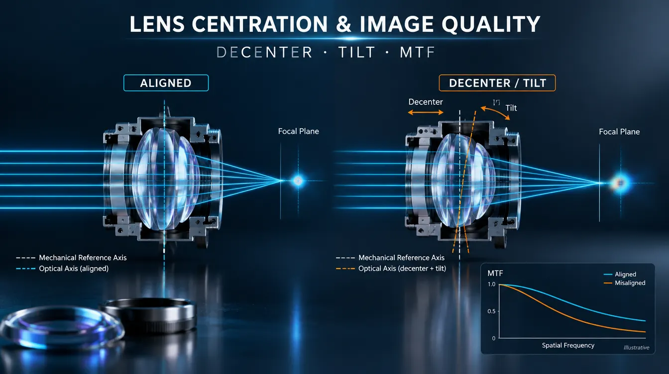
A lens can meet its specified radius, surface quality and center thickness tolerances yet still produce poor image quality after assembly. One side of the image may appear softer than the other, a focused spot may become asymmetric, or fine details may lose contrast even when the system is correctly focused.
One possible cause is lens centration error.
Lens centration describes how accurately the optical geometry of a lens is aligned with a defined reference axis. When this alignment is incorrect, light may travel through the optical system differently from the intended design. Depending on the lens configuration, the resulting errors can include image displacement, coma, astigmatism and reduced modulation transfer function (MTF).
The key engineering point is that centration is not simply a manufacturing dimension. It connects individual lens geometry, mechanical mounting and the final imaging performance of the optical assembly.
What Is Lens Centration?
In precision optics, lens centration refers to the relationship between the optical geometry of a lens and a specified reference axis.
Three axes or references are particularly important:
- Optical axis: The axis defined by the optical design or optical surfaces, as applicable to the component.
- Mechanical axis: The geometric axis associated with the lens edge, mounting diameter or other mechanical features.
- Assembly reference axis: The axis established by the lens barrel, mechanical cell or another optical element.
For an ideal, rotationally symmetric spherical lens, the relevant optical geometry is associated with its surface centers of curvature. For an aspheric lens, the designed aspheric axis also becomes important.
A centration error occurs when the relevant optical features are displaced or tilted relative to the specified datum.
Consider a lens mounted inside a cylindrical barrel. The lens may fit the barrel correctly, but its optical geometry may not be aligned with the mounting diameter. The mechanical assembly can therefore appear properly centered while the transmitted light follows an unintended path.
Centration must consequently be evaluated against a clearly defined reference rather than described simply as whether a lens looks symmetrical.
How Lens Centration Errors Affect Image Quality
The optical consequences depend on lens power, aperture, position within the system and the magnitude and direction of the alignment error.
1. Image Displacement and Optical Axis Deviation
A decentered optical element can alter the direction of transmitted rays and displace the position of an image or focused spot.
In a camera or imaging assembly, this may appear as image displacement or boresight error. In a collimating system, misalignment may cause the output beam to travel at an unintended angle.
Image displacement does not necessarily mean the image is blurred. A lens system may experience a positional shift without a substantial loss of sharpness.
However, when decentration also introduces aberrations, the image can become both displaced and degraded.
This distinction matters when diagnosing a system that fails positional accuracy requirements but still produces apparently sharp images.
2. Coma and Asymmetric Spot Formation
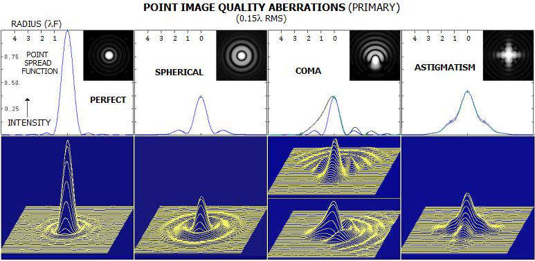
Coma is an aberration in which light from a point object forms an asymmetric image rather than the intended compact spot.
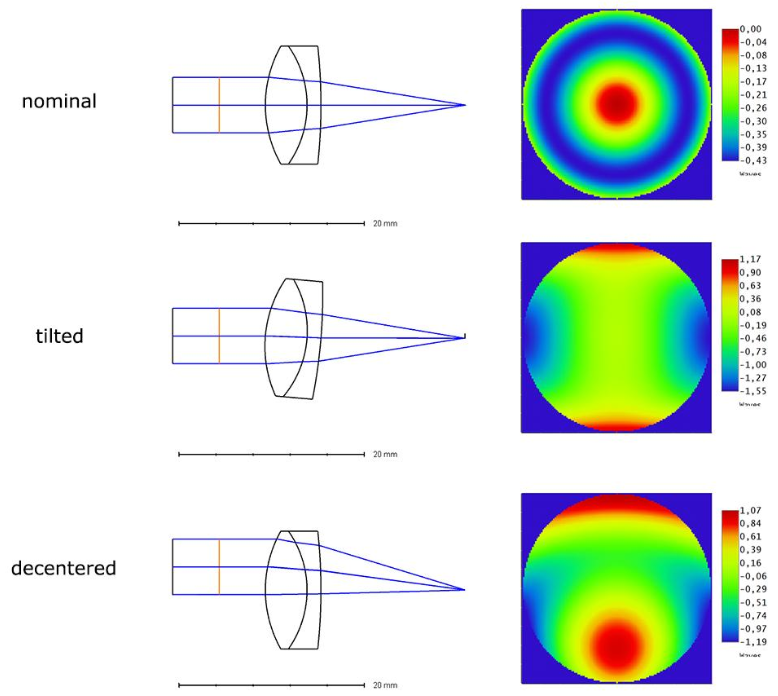
In a centered rotationally symmetric imaging system, on-axis coma is ideally absent. Decentering or tilting a sensitive lens element can break this symmetry and introduce coma even for an on-axis object.
The resulting point-spread function may become elongated or develop a comet-like distribution.
This can affect applications requiring precise localization of small features, including machine vision, optical measurement and high-resolution imaging.
The amount of induced coma is not determined by decentration alone. Optical power, aperture stop location and the configuration of surrounding elements all influence sensitivity.
3. Astigmatism and Uneven Focus
Centration and tilt errors can also contribute to astigmatism, depending on the optical configuration.
Astigmatism occurs when rays associated with different orientations do not converge to the same focal position.
An imaging system affected by alignment-induced astigmatism may show differences in horizontal and vertical feature sharpness.
The operator may find that adjusting focus improves details in one orientation while reducing sharpness in another.
In multi-element objectives, decenter and tilt errors can interact with existing design aberrations and produce uneven image quality across the field.
An important diagnostic distinction is that astigmatism can also result from the nominal optical design, sensor tilt or mechanical stress. Its presence alone does not prove that lens centration is incorrect.
4. Reduced MTF and Image Contrast
Modulation transfer function describes how effectively an imaging system transfers contrast at different spatial frequencies.
As centration-related aberrations increase, the image of a fine feature can become more spread out. Consequently, contrast at relevant spatial frequencies may decrease.
This effect can be especially important in high-resolution machine vision systems where the sensor must distinguish small features with limited contrast.
A centration problem may produce an asymmetric MTF response across the field. For example, one image corner may show reduced contrast while the opposite corner remains relatively sharp.
In other cases, the central field can also be affected.
A single on-axis MTF measurement is therefore not always sufficient to verify the alignment quality of a multi-element imaging system.
Field-dependent MTF, through-focus measurements and comparisons between image positions may provide more useful diagnostic information.
5. Vignetting and Uneven Illumination
Significant mechanical or optical decentration may also shift the light bundle relative to an aperture or mechanical opening.
If part of the beam becomes obstructed, the system can exhibit asymmetric vignetting or reduced illumination in certain field regions.
This effect depends on the available clear aperture and the relationship between the optical elements, stops and mechanical housing.
It should not be assumed that every centration error produces visible vignetting.
Lens Decenter vs Lens Tilt: What Is the Difference?
Decenter and tilt are related alignment errors, but they describe different physical conditions.
| Parameter | Meaning | Possible optical consequence |
|---|---|---|
| Lateral decenter | Transverse displacement relative to a reference axis | Image shift, asymmetric aberrations |
| Lens tilt | Angular misalignment relative to a reference axis | Beam deviation, coma, astigmatism |
| Surface centration error | Incorrect relationship between optical surface geometry and the specified datum | Optical axis deviation or aberration |
| Assembly misalignment | Incorrect relative positioning of optical elements | Reduced MTF, image asymmetry, alignment sensitivity |
Decenter is commonly expressed as a linear displacement, such as micrometers. Tilt is an angular quantity and may be expressed in degrees, arcminutes or arcseconds.
Centration may also be specified through an angular beam-deviation measurement.
These quantities should not be treated as interchangeable.
For example, a specification of 20 μm decenter does not automatically correspond to a particular beam-deviation angle. The relationship depends on optical geometry, refractive power and the measurement definition.
For this reason, the optical drawing should state not only the tolerance value but also the datum and characteristic being controlled.
Why Some Optical Systems Are More Sensitive to Centration
Not every imaging system responds equally to the same amount of lens misalignment.
A small decenter in one element may have little effect, while a similar displacement in another element can substantially reduce performance.
Several factors influence the sensitivity.
Lens Power and Position
The optical power of the displaced element and its location relative to the aperture stop affect how alignment errors influence transmitted rays.
Strongly powered elements or surfaces in sensitive locations may require tighter positional control.
For a multi-element lens, the relative alignment between surfaces can be more important than the position of an individual lens with respect to the external barrel.
Aperture and F-Number
Fast optical systems generally involve wider ray bundles and can be more sensitive to certain alignment-induced aberrations.
Stopping down may reduce some aberration effects, but it also reduces light throughput and can increase diffraction-related resolution loss.
Therefore, reducing the aperture is not a universal solution to poor centration.
Spherical vs Aspheric Lenses
Spherical and aspheric surfaces have different alignment considerations.
A rotationally symmetric aspheric surface has a defined symmetry axis that must be correctly related to the rest of the optical design.
Misalignment of this axis can introduce aberrations that reduce the benefit of the aspheric correction.
Aspheric lenses are not automatically more sensitive in every configuration, but their alignment requirements deserve particular attention when evaluating high-performance imaging systems.
Multi-Element Assemblies
In an objective containing several optical elements, centration errors may interact.
Errors can sometimes partially compensate for one another, but they may also accumulate or reinforce unwanted aberrations.
This is why optical designers use tolerance analysis rather than assigning the same centration requirement to every surface.
The final tolerance should reflect the complete optical system and its required performance.
How Is Lens Centration Measured?
Centration inspection requires a defined reference axis and a measurement method appropriate to the optical component.
Several approaches are commonly used in precision optical manufacturing and inspection.
Reflection-Based Centration Measurement
In reflection-based testing, an autocollimation arrangement can measure the position of a spherical surface’s center of curvature relative to a precision rotation axis.
As the lens rotates, a surface whose center of curvature is displaced from the reference axis produces a changing reflected image position.
The measured runout can be used to determine the surface’s centration error.
This approach helps identify individual surface alignment errors and is useful for evaluating lens geometry.
Transmission-Based Centration Measurement
Transmission-based testing evaluates the behavior of light passing through the optical element.
A collimated beam or target is transmitted through the lens, and the resulting image position is observed as the component rotates.
Movement of the transmitted image provides information about the optical alignment.
However, transmission testing measures a combined optical effect. It may not identify which individual surface causes the error.
Reflection and transmission measurements are complementary rather than automatically equivalent.
Their results should be interpreted according to the defined optical geometry and measurement method.
Assembly-Level Optical Verification
A single lens may satisfy its centration requirement but become misaligned when installed in a mechanical cell.
Possible causes include mechanical clearance, lens seating conditions, adhesive displacement and assembly alignment errors.
For demanding imaging applications, component-level inspection should therefore be distinguished from assembled-system verification.
System-level checks may include field-dependent MTF, image displacement, boresight, spot shape or wavefront performance, depending on the application.
Related reading: How Lens Mounting Stress Affects Optical Performance.
How to Specify Lens Centration on an Optical Drawing
A useful centration tolerance must tell the manufacturer what feature is controlled, what reference is used and how acceptance will be determined.
ISO 10110-6:2025 provides drawing indication rules for centring and tilt tolerances of optical elements and assemblies.
The standard addresses a range of optical geometries, including spherical, aspheric and other surface types.
For a custom lens, engineers should consider the following information:
- Datum definition: Identify the mechanical or optical reference against which centration is evaluated.
- Controlled feature: State whether the requirement applies to a surface, an optical axis or an assembled group.
- Tolerance type and value: Define the permitted angular or linear deviation using the appropriate specification.
- Optical geometry: Provide the required radii, thicknesses, aspheric definitions and mechanical dimensions.
- Measurement method: Identify the required inspection approach where necessary to avoid ambiguity.
- Acceptance criteria: Define the applicable tolerances and any required inspection records.
For a multi-element assembly, it may also be necessary to identify which surfaces establish the common reference axis.
The goal is not to add the smallest possible tolerance to every feature. It is to control those deviations that materially affect system performance.
How Tight Should a Lens Centration Tolerance Be?
There is no single centration tolerance that is appropriate for all optical lenses.
A simple focusing element used for light collection may tolerate substantially different alignment errors from an element in a high-resolution objective.
Similarly, a lens used in a laser beam delivery system may be evaluated against beam pointing or coupling efficiency rather than image MTF.
The tolerance should follow the system’s optical performance requirements.
An effective process begins with an optical tolerance analysis. Each relevant element is displaced or tilted within candidate limits, and the resulting performance is evaluated.
Depending on the application, the acceptance metric may include MTF, RMS spot radius, wavefront error, chief-ray deviation or another suitable quantity.
A tighter centration tolerance generally demands greater control over fabrication, edging, mounting or alignment.
It may also increase inspection requirements and manufacturing cost.
The economically appropriate tolerance is therefore the one that achieves the required optical performance with an acceptable manufacturing and verification process.
Troubleshooting Poor Image Quality Caused by Misalignment
Suppose a machine vision camera produces sharp images near the center but noticeably softer details on one side.
Replacing the sensor or adjusting focus may not solve the problem.
A practical investigation begins by recording the image quality across the field under controlled target distance, aperture, wavelength and focus settings.
The next step is to determine whether the asymmetry changes with lens orientation or mechanical adjustment.
Where the mechanical design permits, controlled rotation and alignment checks can help distinguish optical assembly problems from sensor alignment or target-position errors.
Engineers should also inspect the influence of mounting stress, incorrect spacing and sensor tilt.
If a centration error is suspected, the relevant surfaces or optical elements can be evaluated against the assembly datum using a suitable metrology method.
This sequence avoids attributing every asymmetric image defect to the lens itself.
Lens Centration Requirements for Custom Optical Components
Centration becomes particularly important when individual optical components will be integrated into an existing mechanical assembly.
A lens that meets its surface-form and dimensional requirements may still cause system-level alignment problems if its optical reference is not compatible with the intended mounting arrangement.
At GIAI Photonics, custom optical projects can be reviewed against drawings, optical requirements, material selection, geometry, coating requirements and inspection criteria.
The manufacturing route may involve grinding, polishing, edging, geometry processing, coating and inspection as appropriate to the component.
For projects involving defined centration requirements, the relevant datum, tolerance type, measurement expectations and final application should be included in the technical review.
This does not imply that one fixed centration grade applies to every GIAI lens. Feasibility and inspection requirements must be evaluated for the specific design.
Explore GIAI’s Optical Lenses portfolio and Quality Assurance approach for more information about component specifications and project-level verification.
Frequently Asked Questions
Does lens centration affect image sharpness?
Yes. Centration errors can introduce or increase aberrations that spread light away from its intended image position. Depending on the optical design, this may reduce sharpness, contrast and MTF. However, small alignment errors can also produce image displacement without a significant loss of resolution.
Can a lens have good surface quality but poor centration?
Yes. Surface quality, surface form and centration describe different characteristics. A lens can have acceptable surface finish and surface figure while its optical geometry is misaligned with its specified mechanical reference.
Is lens decenter the same as lens tilt?
No. Decenter describes a lateral displacement, while tilt describes an angular misalignment. Both can affect imaging performance, but their optical consequences and measurement definitions differ.
Is a centration tolerance of 1 arcminute sufficient?
Not necessarily. Whether 1 arcminute is acceptable depends on the optical configuration, reference definition, measurement method and required system performance. The appropriate limit should be established through tolerance analysis rather than selected as a universal value.
Can image processing correct lens centration errors?
Image processing can compensate for certain geometric displacement or distortion effects, but it cannot fully recover optical information lost because of aberration-induced blur or insufficient MTF. Mechanical and optical alignment should be addressed before relying on software correction.
Conclusion
Lens centration affects more than the geometric position of an optical element.
Depending on the system, decenter and tilt can cause image displacement, asymmetric aberrations, uneven field sharpness and reduced MTF.
For precision imaging applications, the important requirement is not simply to minimize a centration number. It is to maintain the relationship between optical surfaces, mechanical references and assembly alignment within limits that preserve the specified system performance.
Clear datum definitions, design-based tolerance allocation and appropriate component and assembly inspection help translate optical requirements into manufacturable specifications.
For a custom lens or optical assembly, contact GIAI Photonics with your drawing, material, optical geometry, centration requirements and intended application for a project-specific technical review.
Technical References
- ISO 10110-6:2025 — Optics and photonics — Preparation of drawings for optical elements and systems — Part 6: Centring and tilt tolerances.
https://www.iso.org/standard/82181.html - TRIOPTICS — Centration Measurement: Principles and Alignment of Lenses and Lens Systems.
- Edmund Optics — Understanding Optical Specifications.
- Edmund Optics — Precision Tolerances for Spherical Lenses.