
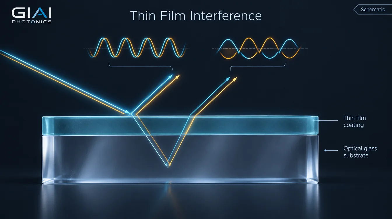
Thin film interference works by splitting one light wave into two or more reflected waves, one from the top surface of a film and one from the bottom. Because the second wave travels an extra optical path of about 2nd cos θ, and each reflection may add a half-wave phase flip, the waves recombine either in phase (reflection is reinforced) or out of phase (reflection is cancelled). Which one happens depends on wavelength, film thickness, refractive index and angle of incidence.
The same physics explains the colors of a soap bubble and the performance of an anti-reflection coating, a laser mirror or a narrow bandpass filter. The difference is control: in an optical coating, every layer’s index and thickness is chosen so that interference happens at the right wavelengths, for the right angle and polarization. This guide explains the two conditions that decide the result, why the film has to be thin, how multilayer stacks turn the effect into filters and mirrors, and what shifts a thin-film spectrum once it is installed in a real system.
How thin film interference works: two reflections, one phase comparison
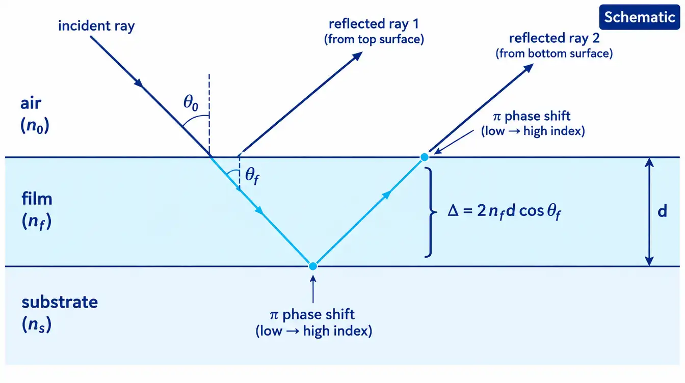
Consider light arriving at a transparent film of refractive index nf and physical thickness d, sitting between an incident medium n0 (usually air) and a substrate ns. At the first interface part of the light reflects (beam 1) and part enters the film. At the second interface another fraction reflects, travels back up through the film and exits parallel to beam 1 (beam 2). Further internal bounces add weaker beams, but the first two already show the mechanism.
What you measure as “reflectance” is the intensity of the sum of these waves, not the sum of their intensities. If the crests line up, the reflected amplitudes add. If a crest meets a trough, they subtract. Energy is not destroyed: for a non-absorbing film, light that is not reflected is transmitted, so R + T = 1 at each wavelength.
Two quantities decide whether the waves meet in phase or out of phase: the optical path difference inside the film and any phase change that happens at the reflections themselves.
The two conditions that decide constructive or destructive interference
1. Optical path difference
Beam 2 crosses the film twice. The extra distance that matters is the optical path, which is the physical path multiplied by the film’s refractive index:
where θf is the propagation angle inside the film, found from Snell’s law (n0 sin θ0 = nf sin θf). At normal incidence cos θf = 1.
The product nfd is the film’s optical thickness. Coating designers usually work in optical thickness, not nanometres of material, because it is optical thickness that sets where interference features fall on the wavelength axis. A “quarter-wave layer” is a layer with nfd = λ0/4 at the design wavelength λ0; its round-trip optical path is λ0/2.
Notice the cos θf term. Tilting the film shortens the effective path difference, which is why every interference coating shifts toward shorter wavelengths as the angle of incidence (AOI) increases.
2. Phase change on reflection
For non-absorbing dielectric materials at or near normal incidence, a reflection from a lower-index to a higher-index medium adds a phase shift of π (half a wave). A reflection from a higher-index to a lower-index medium adds no phase shift. Combining this with the path difference gives the familiar conditions:
| Index sequence | Phase flips at the two interfaces | Reflection minimum when | Reflection maximum when |
|---|---|---|---|
| n0 < nf < ns (e.g. MgF2 on glass) | Both reflections flip: relative flip cancels | 2nfd = (m + ½)λ | 2nfd = mλ |
| nf greater than both neighbours (e.g. soap film in air, high-index layer on glass) | Only the first reflection flips | 2nfd = mλ | 2nfd = (m + ½)λ |
| nf lower than both neighbours (e.g. air gap between two glass plates) | Only the second reflection flips | 2nfd = mλ | 2nfd = (m + ½)λ |
This rule has limits that matter in engineering. Metals and absorbing films produce phase shifts that are neither 0 nor π, which is why metal-dielectric designs cannot be analysed with the simple table above. At oblique incidence, s- and p-polarized light see different reflection coefficients and phases; for p-polarization the reflection phase behaves differently near Brewster’s angle. Real coating design therefore uses full electromagnetic calculation, typically the characteristic (transfer) matrix method, rather than counting half-wave flips.
Why the film has to be thin: coherence
Interference only appears if the two reflected waves are still coherent with each other when they recombine. The extra path 2nfd must be shorter than the coherence length of the light. Optical coating layers are typically tens to a few hundred nanometres thick, well inside the coherence length of ordinary broadband sources, so their interference is stable and predictable.
A glass substrate a few millimetres thick behaves differently. Under broadband or moderately narrowband illumination, the reflection from its back surface adds in intensity rather than in amplitude, with no stable fringes. Two practical consequences follow:
- The back surface of a coated window or filter contributes its own reflection, roughly 4% per uncoated surface for glass with n ≈ 1.5 in air at normal incidence. A spectrophotometer measuring the part sees both sides.
- With highly coherent sources such as single-frequency lasers, even a thick plate can produce etalon fringes. Wedged substrates or an AR coating on the second surface are common countermeasures.
Worked example: a single-layer anti-reflection coating
The simplest useful thin-film device is a quarter-wave anti-reflection (AR) layer. For the two reflected waves to cancel completely at one wavelength, they must be π out of phase and equal in amplitude. The quarter-wave thickness handles the phase. Equal amplitude requires the film index to be the geometric mean of its neighbours:
Valid for a single quarter-wave, non-absorbing layer at normal incidence, at the design wavelength.
For crown glass such as N-BK7 (ns ≈ 1.517 near 550 nm) in air, the ideal index would be about 1.23. No durable solid coating material has an index that low, so magnesium fluoride (n ≈ 1.38) is the usual practical choice. The numbers below are calculated for one surface, ignoring the back surface and material dispersion:
| Surface condition | Reflectance at 450 nm | Reflectance at 550 nm (design) | Reflectance at 700 nm |
|---|---|---|---|
| Uncoated glass, n = 1.517 | ≈ 4.2% | ≈ 4.2% | ≈ 4.2% |
| Quarter-wave MgF2 (n = 1.38) at 550 nm | ≈ 1.6% | ≈ 1.3% | ≈ 1.6% |
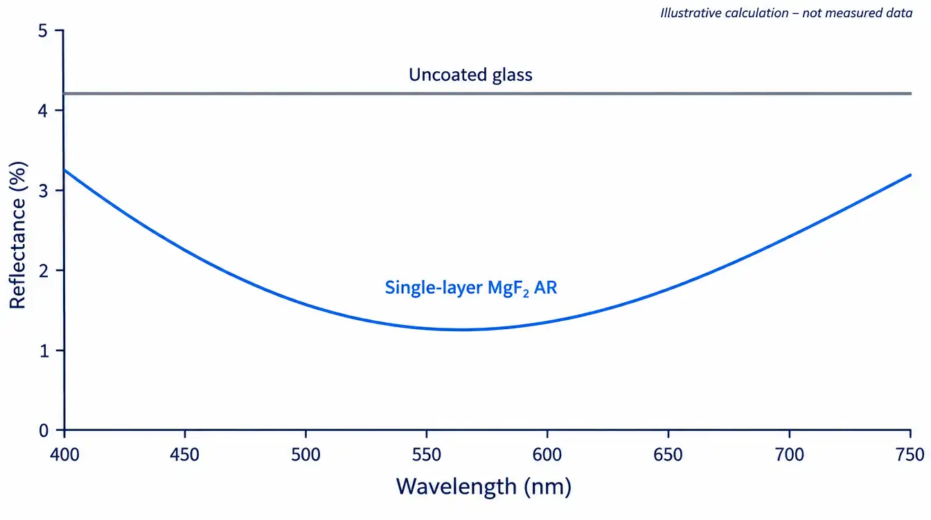
Two lessons come out of this example. First, interference can only cancel reflection fully when both phase and amplitude conditions are met, and material availability limits the amplitude match. Second, the cancellation is wavelength-specific: away from 550 nm the quarter-wave condition is no longer exact and reflectance rises. Lower residual reflectance, or a wider low-reflection band, requires additional layers. That is the step from a single layer to multilayer V-coats and broadband designs, compared in our guide to V-coat vs broadband AR coating.
How multilayer stacks turn interference into filters and mirrors
A multilayer coating repeats the same mechanism at every interface. With dozens or hundreds of layers, the reflected waves from all interfaces add up, and the designer can shape where they reinforce and where they cancel. Three building blocks cover most dielectric coatings.
Quarter-wave stack: the dielectric mirror
Alternate high-index (H) and low-index (L) layers, each a quarter-wave thick at λ0. At that wavelength, every reflected wave returns in phase with the others, so reflectance grows quickly with the number of layer pairs:
| Layer pairs (N) | Total layers | Calculated reflectance at λ0 |
|---|---|---|
| 2 | 5 | ≈ 72.5% |
| 4 | 9 | ≈ 92.8% |
| 6 | 13 | ≈ 98.3% |
| 8 | 17 | ≈ 99.6% |
| 10 | 21 | ≈ 99.90% |
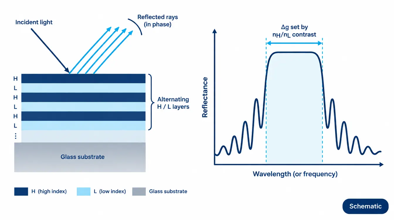
The high-reflectance zone has a finite width. For an ideal quarter-wave stack at normal incidence, its full width expressed in relative wavenumber g = λ0/λ is:
With nH = 2.10 and nL = 1.46, Δg ≈ 0.23. Centred at 1064 nm, that places the edges of the reflection band near 954 nm and 1202 nm. The width is set by the index contrast, not by the number of layers; adding pairs raises peak reflectance and steepens the edges but does not widen the band. Wider bands need higher contrast materials or stacked designs with shifted centre wavelengths. The trade-offs against metal mirrors are covered in dielectric coating vs metallic coating.
Fabry–Pérot cavity: the bandpass filter
Place a spacer layer, typically with an optical thickness of an integer number of half-waves at λ0, between two quarter-wave mirrors. Inside the stop band of the mirrors, light is reflected, except at the resonance where the round-trip phase through the cavity allows multiple-beam transmission. The result is a narrow transmission peak at the centre wavelength. Higher mirror reflectance narrows the passband; coupling several cavities squares off its shape and steepens the edges. This is the basic structure of an interference filter. Outside the mirror stop band, transmission returns, which is why bandpass filters need additional blocking layers or absorbing glass to reach the required optical density over a broad range.
Edge filters, dichroics and beamsplitters
Longpass and shortpass filters, dichroic mirrors and beamsplitters use modified quarter-wave stacks, with the outer layers adjusted to suppress ripple on the transmitting side of the edge. Each design is still governed by the same two conditions: optical path difference and phase on reflection, evaluated across many interfaces at once.
What shifts a thin-film spectrum in a real optical system
Because the interference condition depends on optical thickness and angle, anything that changes n, d or θ changes the spectrum. These variables are where most field problems come from.
| Variable | Effect on the spectrum | Engineering implication |
|---|---|---|
| Angle of incidence | Features shift to shorter wavelengths as AOI increases | Specify and test at the AOI used in the system |
| Polarization (oblique incidence) | s and p features separate; edges split and passbands can broaden | State polarization or require average-polarization performance |
| Converging or diverging beam | Passband shifts and broadens because rays arrive at a range of angles | Specify cone half-angle, not just chief-ray AOI |
| Layer thickness error | A uniform thickness error of ε scales the spectrum by about ε (non-dispersive approximation) | Tight CWL tolerances need deposition control and measurement |
| Moisture in porous films | Adsorbed water raises effective index; spectrum shifts toward longer wavelengths | Denser deposition processes reduce this shift |
| Temperature | Index and thickness change slightly; small spectral drift | Matters for narrowband filters across wide temperature ranges |
| Absorption and scatter | Lower peak transmission and reflectance than the ideal design | Limits how close R or T can approach 100% |
For collimated light, the AOI shift of a bandpass filter is commonly estimated with:
n* is the filter’s effective index, which depends on the design and the polarization, so the result is an estimate.
As an illustrative example, an 850 nm filter with n* = 1.8 in air shifts by about 4 nm at 10° and by about 15 nm at 20°. With n* = 2.0 the same angles give about 3 nm and 13 nm. For a 10 nm wide passband, either result can move the passband off the source line. The polarization side of this effect is explained in how polarization affects optical filter spectra at oblique incidence, and the converging-beam case in cone half-angle effect on interference filters. Moisture- and temperature-related shifts depend strongly on film density; see IBS vs IAD optical coating and optical filter temperature drift.
Common misunderstandings about thin film interference
- “Destructive interference destroys light.” It redistributes it. In a lossless coating, reduced reflection appears as increased transmission.
- “A quarter-wave layer is a quarter of the wavelength thick.” It is a quarter-wave in optical thickness at the design wavelength inside the material, so the physical thickness is λ0/(4nf).
- “More layers always widen the reflection band.” In a quarter-wave stack, more layers raise reflectance and steepen the edges; index contrast sets the bandwidth.
- “A filter spec is valid at any angle.” Interference coatings are designed for a specific AOI and beam geometry. Performance at other angles must be calculated or measured.
- “The half-wave phase flip rule always applies.” It applies to non-absorbing dielectrics near normal incidence. Metals, absorbing layers and oblique p-polarized light need full calculation.
- “A thicker spacer is always better.” Higher-order cavities and thick layers narrow features but increase sensitivity to angle, thickness error and stress.
How thin-film interference performance is verified
Because the effect is wavelength-, angle- and polarization-dependent, a measured curve is only meaningful together with its test conditions.
- Spectrophotometry at the specified AOI. Transmission and/or reflection are measured over the required range, at normal incidence or at the design angle with an angle accessory. For oblique use, s, p or average polarization should be stated.
- Accounting for the back surface. A transmission measurement of a part includes both surfaces. Reflectance of a single coated surface is often measured on a witness sample with a roughened or index-matched back surface, or calculated by correcting for the second surface.
- Blocking measurement. High optical density requires an instrument and method with enough dynamic range; otherwise the curve shows the instrument floor, not the filter.
- Film characterization during development. Ellipsometry or spectral fitting of single-layer samples is commonly used to determine refractive index and thickness of each material before a multilayer design is run.
- Environmental checks when relevant. If the coating will see humidity or temperature cycling, measuring the spectrum before and after exposure shows whether the interference condition has drifted.
For more on reading the resulting data, see optical filter spectral tolerance explained.
What to specify for a custom interference coating
Because the physics ties performance to wavelength, angle, polarization and substrate, a useful coating specification states the conditions as clearly as the targets:
- Wavelength range and target values: transmission, reflection or OD, with the wavelength band for each
- AOI, plus cone half-angle if the beam is not collimated
- Polarization state (s, p, average or unpolarized)
- Substrate material, thickness and whether the second surface is coated
- Coated area, clear aperture and part geometry
- Operating environment: temperature range, humidity, cleaning method
- Measurement method and acceptance criteria
GIAI Photonics reviews custom coating and filter projects against the drawing, optical requirements, substrate, geometry, coating conditions and inspection criteria before defining the manufacturing route. More background on related coating topics is collected in the Filters & Coatings resource hub.
FAQ
Why does an AR-coated lens still show a colored reflection?
A single-layer or simple AR coating cancels reflection best near its design wavelength, often in the green. Reflection at the blue and red ends remains higher, so the residual reflected light looks purple or magenta. The color is a direct view of the wavelength dependence of thin film interference, not a defect. Broadband multilayer designs reduce and flatten the residual reflection, and their tint depends on the design.
Why does an interference filter shift to shorter wavelengths when tilted?
The phase difference between reflected waves depends on 2nd cos θ. Tilting the filter increases the internal angle and reduces cos θ, so the interference condition is satisfied at a shorter wavelength. The size of the shift depends on the angle and on the filter’s effective index, and at oblique incidence it differs between s and p polarization.
Can thin film interference produce 100% reflection or zero reflection?
Ideal lossless designs can approach either limit at a design wavelength, but real coatings are limited by absorption, scatter, finite layer count and thickness errors. Reflectance and residual reflectance should be specified with a wavelength band, AOI and measurement method rather than as absolute values.
Does thin film interference happen in the substrate as well?
Under broadband light, a substrate millimetres thick is far beyond the coherence length, so its two surfaces add their reflections in intensity and produce no stable fringes. With highly coherent laser light, a plane-parallel substrate can act as an etalon, which is why wedged windows or second-surface AR coatings are used in laser systems.
Why do soap bubbles show changing colors while coatings look stable?
A soap film’s thickness varies from place to place and changes as it drains and evaporates, so the wavelengths that interfere constructively change across its surface. In an optical coating, layer thickness and index are controlled during deposition, so the interference condition stays in a defined, measurable position.
Working on a coating or filter where interference conditions matter? Send the drawing or specification together with the wavelength range, target T/R/OD, AOI, polarization, substrate, coated area and inspection criteria to GIAI Photonics for technical review.